-
-
开发板:ArmSoM-W3
-
Kernel:5.10.160
-
OS:Debian11
-
本⽂主要介绍在Rockchip平台下Camera相关代码配置,MIPI-CSI调试的通路解析
名词解释:
-
CSI ( Camera Serial Interface ):主机处理器与摄像头模块之间的高速串行接口
-
DSI ( Display Serial Interface ):主机处理器与显示模块之间的高速串行接口
-
ISP ( Image Signal Processor ): 即图像信号处理模块, 主要作用是对前端图像传感器输出的信号做后期处理,依赖于 ISP 才能在不同的光学条件下都能较好的还原现场细节。
-
VICAP( Video capture ):视频捕获单元
-
MIPI-DPHY :Rockchip芯片中符合MIPI-DPHY协议的控制器。
二. MIPI-CSI基础概念
MIPI:移动产业处理器接口(Mobile Industry Processorinterface) 是MIPI联盟发起的为移动应用处理器制定的开放标准。
CSI: MIPI-CSI-2协议是MIPI联盟协议的子协议,专门针对摄像头芯片的接口而设计。
由于其高速,低功耗的特点,MIPI-CSI2协议极大的支持了高清摄像头领域的发展,CSI-2协议遵循的物理标准有两个,分别为C-PHY和D-PHY。
D-PHY与C-PHY区别: 从实用角度来看,主要是数据线和时钟线的区别,还有传输速率,C-PHY通过某些技术改良,使数据传输速度更快。
瑞芯微3588用的DPHY-v1.2 &&(D/C-PHY) DPHY-v2.0。
三. MIPI-CSI硬件配置
RK3588 camera 资源硬件拥有2路DCPHY,2路DPHY,一路DVP,6路CSI HOST,一个vicap控制器,2个isp控制器。 其中2路DPHY可以分解成4x2lane的模式工作。
硬件通路框图如下:
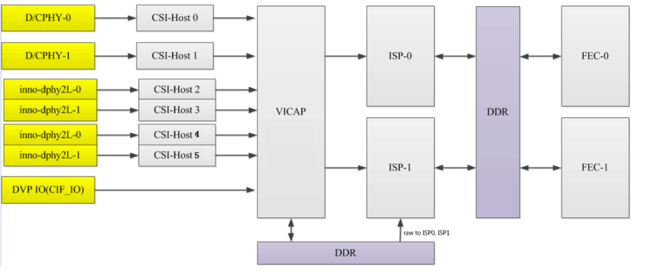
armsom-camera-channel
MIPI-CSI资源介绍 :
| Type | Max bandwidth | NUM | Mode |
|---|---|---|---|
| DPHY-v1.2 | 2.5Gbps x 4 lanes | 2 | 4lane or 2lane+2lane |
| (D/C-PHY) DPHY-v2.0 | DPHY-v2.0: 2.5Gbps x 2lanes | 2 | DPHY-v2.0: 2lane |
| CSI-Host | For MIPI D-PHY v1.2/D-PHY v2.0/C-PHY v1.1 | 6 |
2lane最大带宽是5G,分辨率可以达到8M30帧,4lane最大带宽达到10G。
三. MIPI CSI用法
3.1 DPHY
-
rk3588支持两个dcphy,节点名称分别为csi2_dcphy0/csi2_dcphy1。每个dcphy硬件支持RX/TX 同时使用,对于camera输入使用的是RX。支持DPHY/CPHY协议复用;需要注意的是同一个dcphy的TX/RX 只能同时使用DPHY或同时使用CPHY
-
rk3588支持2个dphy硬件,这里我们称之为dphy0_hw/dphy1_hw,两个dphy硬件都可以工作在full mode 和split mode两种模式下
Full Mode: 仅使用csi2_dphy0,csi2_dphy0与csi2_dphy1/csi2_dphy2互斥,不可同时使用;
data lane最大4 lanes;
最大速率2.5Gbps/lane;
Split Mode: 仅使用csi2_dphy1和csi2_dphy2, 与csi2_dphy0互斥,不可同时使用;
csi2_dphy1和csi2_dphy2可同时使用;
csi2_dphy1和csi2_dphy2各自的data lane最大是2 lanes;
csi2_dphy1对应物理dphy的lane0/lane1;
csi2_dphy2对应物理dphy的lane2/lane3;
最大速率2.5Gbps/lane;
3.2 多sensor支持
硬件支持最多采集7路sensor:6mipi + 1dvp,多sensor软件通路如下:

armsom-camera-connect
四. camera相关配置
4.1 Camera 软件驱动目录
Camera相关驱动文件如下:
|-- arch/arm/boot/dts DTS配置文件
|-- drivers/phy/rockchip
|-- phy-rockchip-mipi-rx.c mipi dphy驱动
|-- phy-rockchip-csi2-dphy-common.h
|-- phy-rockchip-csi2-dphy-hw.c
|-- phy-rockchip-csi2-dphy.c
|-- drivers/media
|-- platform/rockchip/cif RKCIF驱动
|-- platform/rockchip/isp RKISP驱动
|-- dev 包含 probe、异步注册、clock、pipeline、 iommu及media/v4l2 framework
|-- capture 包含 mp/sp/rawwr的配置及 vb2,帧中断处理
|-- dmarx 包含 rawrd的配置及 vb2,帧中断处理
|-- isp_params 3A相关参数设置
|-- isp_stats 3A相关统计
|-- isp_mipi_luma mipi数据亮度统计
|-- regs 寄存器相关的读写操作
|-- rkisp isp subdev和entity注册
|-- csi csi subdev和mipi配置
|-- bridge bridge subdev,isp和ispp交互桥梁
|-- platform/rockchip/ispp rkispp驱动
|-- dev 包含 probe、异步注册、clock、pipeline、 iommu及media/v4l2 framework
|-- stream 包含 4路video输出的配置及 vb2,帧中断处理
|-- rkispp ispp subdev和entity注册
|-- params TNR/NR/SHP/FEC/ORB参数设置
|-- stats ORB统计信息
|-- i2c
|-- imx415.c CIS(cmos image sensor)驱动
4.2 Sensor驱动开发移植
Sensor 驱动位于 drivers/media/i2c 目录下,Sensor 驱动与 RKCIF 或者 RKISP1 驱动最大程度上独立,二者异步注册,在dts中由 remote-endpoint 声明 连接关系。
Sensor 驱动的开发移植概括为 5 个部分
-
按照 datasheet 编写上电时序,主要包括 vdd、reset、powerdown、clk 等
-
配置 sensor 的寄存器以输出所需的分辨率、格式
-
编写 struct v4l2_subdev_ops 所需要的回调函数,一般包括 set_fmt、get_fmt、s_stream、s_power
-
增加 v4l2 controller 用来设置如fps、exposure、gain、test pattern
-
编写 probe()函数,并添加 Media Control 及 Sub Device 初始化代码
Documentation/devicetree/bindings/media/i2c/下面有对驱动的Documentation可供参考,板级 dts 可以根据该文档快速配置。
在板级 dts 中,引用 Sensor 驱动,一般需要:
-
配置正确的 clk及io mux
-
根据原理图设置上电时序所需要的 regulator 及 gpio
-
增加 port 子节点,与 cif 或者 isp 建立连接
4.2.1 上电时序
不同 Sensor 对上电时序要求不同,可能很大部分的 Sensor 对时序要求不严格,只要 mclk、vdd、reset 和 powerdown 状态是对的、就能正确进行 I2C 通讯并输出图片,而不用关心上电的先后顺序及延时, Sensor 厂家提供的 DataSheet 中,一般会有上电时序图,只需要按顺序配置即可。
__imx415_power_on() //控制上电时序部分
__imx415_power_off() //控制下电时序部分
在probe()阶段会去尝试读取 chip id,如 imx415的 imx415_check_sensor_id,
ret = __imx415_power_on(imx415);
if (ret)
goto err_free_handler;
ret = imx415_check_sensor_id(imx415, client);
if (ret)
goto err_power_off;
如果能够正确读取到chip id,一般就认为上电时序正确,Sensor 能够正常进行 i2c 通信
一般在imx415_check_sensor_id()中出现问题、按照以下方式排查
-
先将__imx415_power_off()注释掉
-
检查i2c从地址、i2c读函数
-
可以抓下i2c的波形
4.2.2 Sensor 初始化寄存器列表
在imx415的驱动中,定义了struct imx415_mode supported_modes[],用来表示Sensor 支持的不同初始化 mode,即Sensor可以输出不同分辨率的图像、不同的fps等。Mode 可以包括如分辨率,Mbus Code,fps,寄存器初始化列表等。
static const struct imx415_mode supported_modes[] = {
    /*
     * frame rate = 1 / (Vtt * 1H) = 1 / (VMAX * 1H)
     * VMAX >= (PIX_VWIDTH / 2) + 46 = height + 46
     */
    ......
    {
        /* 1H period = (1100 clock) = (1100 * 1 / 74.25MHz) */
        .bus_fmt = MEDIA_BUS_FMT_SGBRG12_1X12,
        .width = 3864,
        .height = 2192,
        .max_fps = {
            .numerator = 10000,
            .denominator = 300000,
        },
        .exp_def = 0x08ca - 0x08,
        .hts_def = 0x044c * IMX415_4LANES * 2,
        .vts_def = 0x08ca,
        .global_reg_list = imx415_global_12bit_3864x2192_regs,
        .reg_list = imx415_linear_12bit_3864x2192_891M_regs,
        .hdr_mode = NO_HDR,
        .mipi_freq_idx = 1,
        .bpp = 12,
        .vc[PAD0] = V4L2_MBUS_CSI2_CHANNEL_0,
    },
    {
        .bus_fmt = MEDIA_BUS_FMT_SGBRG12_1X12,
        .width = 3864,
        .height = 2192,
        .max_fps = {
            .numerator = 10000,
            .denominator = 300000,
        },
        .exp_def = 0x08CA * 2 - 0x0d90,
        .hts_def = 0x0226 * IMX415_4LANES * 2,
        /*
         * IMX415 HDR mode T-line is half of Linear mode,
         * make vts double(that is FSC) to workaround.
         */
        .vts_def = 0x08CA * 2,
        .global_reg_list = imx415_global_12bit_3864x2192_regs,
        .reg_list = imx415_hdr2_12bit_3864x2192_1782M_regs,
        .hdr_mode = HDR_X2,
        .mipi_freq_idx = 3,
        .bpp = 12,
        .vc[PAD0] = V4L2_MBUS_CSI2_CHANNEL_1,
        .vc[PAD1] = V4L2_MBUS_CSI2_CHANNEL_0,//L->csi wr0
        .vc[PAD2] = V4L2_MBUS_CSI2_CHANNEL_1,
        .vc[PAD3] = V4L2_MBUS_CSI2_CHANNEL_1,//M->csi wr2
    },
    ......
};
这里支持很多种imx415模组的分辨率配置,默认是3864x2192@30fp,查看下面代码可知会以一种分辨率来做为默认的配置:
ret = of_property_read_u32(node, OF_CAMERA_HDR_MODE, &hdr_mode);
    if (ret) {
        hdr_mode = NO_HDR;
        dev_warn(dev, " Get hdr mode failed! no hdr default\n");
    }
    imx415->client = client;
    imx415->cfg_num = ARRAY_SIZE(supported_modes);
    for (i = 0; i < imx415->cfg_num; i++) {
        if (hdr_mode == supported_modes[i].hdr_mode) {
            imx415->cur_mode = &supported_modes[i];
            break;
        }
    }
适配新的分辨率需要替换新的初始化列表,例如imx415摄像头,仅支持30帧,但是需要提升到60帧。
sensor本身支持的最大mipi传输速率,每秒传输的数据量是width * height * 10bit * fps,这个也是有上限,不能无限制提高。 IMX415的DateSheet上写的就是支持3864x2192@30fps,要调整为60帧,需要厂家提供一组低分辨率的sensor配置,比如1080P@60fps,然后添加到struct imx415_mode supported_modes[]的.reg_list中,reg_list列表最后用了 REG_NULL 表示结束。
4.2.3 回调函数
v4l2_subdev_ops 回调函数是 Sensor 驱动中逻辑控制的核心,包含丰富的接口给上层应用调用
static const struct v4l2_subdev_ops imx415_subdev_ops = {
    .core   = &imx415_core_ops,
    .video  = &imx415_video_ops,
    .pad    = &imx415_pad_ops,
};
部分成员函数:
-
open- Userspace通过在打开/dev/v4l-subdev?节点时,会调用到该.open()函数。 -
s_power- 包括power on和power off。在这里上电或者下电 -
enum_mbus_code- 用于枚举支持的媒体总线(Media Bus)格式代码。媒体总线是V4L2系统中用于描述图像格式的标准。这个函数可能会列出IMX415传感器支持的不同媒体总线格式代码。 -
enum_frame_size- 用于枚举传感器支持的不同帧尺寸(分辨率)。这个函数可能会返回一组可用的帧尺寸选项,供应用程序选择。 -
enum_frame_interval- 用于枚举传感器支持的不同帧间隔(帧速率)。它会返回可用的帧间隔选项,以供应用程序选择。 -
get_fmt- 用于获取当前传感器的图像格式。应用程序可以使用它来查询当前设置的图像格式。 -
set_fmt- 用于设置传感器的图像格式。应用程序可以使用它来配置所需的图像格式。 -
get_selection- 用于获取当前传感器的图像选择(ROI - Region of Interest)。这允许应用程序了解当前的感兴趣区域设置。 -
get_mbus_config- 用于获取媒体总线配置,包括数据总线宽度、时序等信息。
这些函数在V4L2子设备的驱动程序中起着关键的作用,允许应用程序配置和控制IMX415传感器,以捕获图像和视频数据。
4.3 DTS配置
这里是单路Camera的dts配置说明,以imx415摄像头为例 。
-
案例场景:这里使用的是csi2_dphy0的单路camera配置:
-
链路配置: imx415 —> csi2_dphy0 —> mipi2_csi2 —> rkcif_mipi_lvds2—>rkcif_mipi_lvds2_sditf —>rkisp0_vir2
在这个通路下,会注册medio0和medio1这两个节点。
4.3.1 配置sensor端
我们需要根据板子原理图的MIPI CSI接口找到sensor是挂在哪个I2C总线上,然后在对应的I2C节点配置camera节点,正确配置camera模组的I2C设备地址、引脚等属性。sensor对应驱动路径在kernel\drivers\media\i2c下面。 下面是imx415配置:
&i2c3 {
status = "okay";
imx415: imx415@1a {
status = "okay";
compatible = "sony,imx415";// 需要与驱动中的匹配字符串一致
reg = <0x1a>; // sensor I2C设备地址,7位
clocks = <&cru CLK_MIPI_CAMARAOUT_M3>; // sensor mclk源配置
clock-names = "xvclk";
pinctrl-names = "default";
pinctrl-0 = <&mipim0_camera3_clk>; //sensor 相关电源域使能
power-domains = <&power RK3588_PD_VI>;
pwdn-gpios = <&gpio1 RK_PB0 GPIO_ACTIVE_HIGH>;
reset-gpios = <&gpio4 RK_PA0 GPIO_ACTIVE_LOW>;
rockchip,camera-module-index = <0>;
rockchip,camera-module-facing = "back"; // 模组朝向,有"back"和"front"
rockchip,camera-module-name = "CMK-OT2022-PX1";
rockchip,camera-module-lens-name = "IR0147-50IRC-8M-F20";
port {
imx415_out0: endpoint {
remote-endpoint = <&mipidphy0_in_ucam0>;
data-lanes = <1 2 3 4>;
};
};
};
};
注意:
data-lanes必须指明具体使用的lane数,否则无法识别为mipi 类型;
module-index与iq文件中的moduleId相关,<0>对应moduleId配置为m00,<1>对应moduleId配置为m01,m是“module”的缩写,01是十进制数字;
module-name与module-lens-name命令与设备/etc/iqfiles中对应sensor的iq文件名后面相同。这里对应的Sensor iq文件是“imx415_CMK-OT2022-PX1_IR0147-50IRC-8M-F20.json”,注意大小写有区分
4.3.2 csi2_dphy0配置
csi2_dphy0与csi2_dphy1/csi2_dphy2互斥,不可同时使用。另外需要使能csi2_dphy0_hw物理节点
&csi2_dphy0_hw {
status = "okay";
};
&csi2_dphy0 {
status = "okay";
ports {
#address-cells = <1>;
#size-cells = <0>;
port@0 {
reg = <0>;
#address-cells = <1>;
#size-cells = <0>;
mipidphy0_in_ucam0: endpoint@1 {
reg = <1>;
remote-endpoint = <&imx415_out0>; // sensor端的 port名
data-lanes = <1 2 3 4>;
};
};
port@1 {
reg = <1>;
#address-cells = <1>;
#size-cells = <0>;
csidphy0_out: endpoint@0 {
reg = <0>;
remote-endpoint = <&mipi2_csi2_input>; csi2 host端的port名
};
};
};
};
&mipi2_csi2 {
status = "okay";
ports {
#address-cells = <1>;
#size-cells = <0>;
port@0 {
reg = <0>;
#address-cells = <1>;
#size-cells = <0>;
mipi2_csi2_input: endpoint@1 {
reg = <1>;
remote-endpoint = <&csidphy0_out>;
};
};
port@1 {
reg = <1>;
#address-cells = <1>;
#size-cells = <0>;
mipi2_csi2_output: endpoint@0 {
reg = <0>;
remote-endpoint = <&cif_mipi2_in0>;
};
};
};
};
&rkcif {
status = "okay";
};
&rkcif_mmu {
status = "okay";
};
&rkcif_mipi_lvds2 {
status = "okay";
port {
cif_mipi2_in0: endpoint {
remote-endpoint = <&mipi2_csi2_output>;
};
};
};
4.3.3 isp相关配置
&rkcif_mipi_lvds2_sditf {
status = "okay";
port {
mipi_lvds2_sditf: endpoint {
remote-endpoint = <&isp0_vir0>;
};
};
};
&rkisp0 {
status = "okay";
};
&isp0_mmu {
status = "okay";
};
&rkisp0_vir0 {
status = "okay";
port {
#address-cells = <1>;
#size-cells = <0>;
isp0_vir0: endpoint@0 {
reg = <0>;
remote-endpoint = <&mipi_lvds2_sditf>;
};
};
};
一个ISP可以接多个Sensor,但只能分时复用。通过配置dts,将多个Sensor链接到MIPI DPHY后,可通过media-ctl切换Sensor。
4.4 多摄像头配置
上述是单目4lan摄像头的配置,DPHY处于Full Mode下,这里有一份DPHY处于Split Mode下,配置四个2lan摄像头的例子:
// SPDX-License-Identifier: (GPL-2.0+ OR MIT)
/*
* Copyright (c) 2021 Rockchip Electronics Co., Ltd.
*
*/
/ {
vcc_mipicsi0: vcc-mipicsi0-regulator {
compatible = "regulator-fixed";
gpio = <&gpio1 RK_PB1 GPIO_ACTIVE_HIGH>;
pinctrl-names = "default";
pinctrl-0 = <&mipicsi0_pwr>;
regulator-name = "vcc_mipicsi0";
enable-active-high;
};
vcc_mipicsi1: vcc-mipicsi1-regulator {
compatible = "regulator-fixed";
gpio = <&gpio1 RK_PB2 GPIO_ACTIVE_HIGH>;
pinctrl-names = "default";
pinctrl-0 = <&mipicsi1_pwr>;
regulator-name = "vcc_mipicsi1";
enable-active-high;
};
};
&pinctrl {
cam {
mipicsi0_pwr: mipicsi0-pwr {
rockchip,pins =
<1 RK_PB1 RK_FUNC_GPIO &pcfg_pull_none>;
};
mipicsi1_pwr: mipicsi1-pwr {
rockchip,pins =
<1 RK_PB2 RK_FUNC_GPIO &pcfg_pull_none>;
};
};
};
&csi2_dphy0_hw {
status = "okay";
};
&csi2_dphy1_hw {
status = "okay";
};
&csi2_dphy1 {
status = "okay";
ports {
#address-cells = <1>;
#size-cells = <0>;
port@0 {
reg = <0>;
#address-cells = <1>;
#size-cells = <0>;
mipi_in_ucam2: endpoint@1 {
reg = <1>;
remote-endpoint = <&imx464_out2>;
data-lanes = <1 2>;
};
};
port@1 {
reg = <1>;
#address-cells = <1>;
#size-cells = <0>;
csidphy1_out: endpoint@0 {
reg = <0>;
remote-endpoint = <&mipi2_csi2_input>;
};
};
};
};
&csi2_dphy2 {
status = "okay";
ports {
#address-cells = <1>;
#size-cells = <0>;
port@0 {
reg = <0>;
#address-cells = <1>;
#size-cells = <0>;
mipi_in_ucam3: endpoint@1 {
reg = <1>;
remote-endpoint = <&imx464_out3>;
data-lanes = <1 2>;
};
};
port@1 {
reg = <1>;
#address-cells = <1>;
#size-cells = <0>;
csidphy2_out: endpoint@0 {
reg = <0>;
remote-endpoint = <&mipi3_csi2_input>;
};
};
};
};
&csi2_dphy4 {
status = "okay";
ports {
#address-cells = <1>;
#size-cells = <0>;
port@0 {
reg = <0>;
#address-cells = <1>;
#size-cells = <0>;
mipi_in_ucam4: endpoint@1 {
reg = <1>;
remote-endpoint = <&imx464_out4>;
data-lanes = <1 2>;
};
};
port@1 {
reg = <1>;
#address-cells = <1>;
#size-cells = <0>;
csidphy4_out: endpoint@0 {
reg = <0>;
remote-endpoint = <&mipi4_csi2_input>;
};
};
};
};
&csi2_dphy5 {
status = "okay";
ports {
#address-cells = <1>;
#size-cells = <0>;
port@0 {
reg = <0>;
#address-cells = <1>;
#size-cells = <0>;
mipi_in_ucam5: endpoint@1 {
reg = <1>;
remote-endpoint = <&imx464_out5>;
data-lanes = <1 2>;
};
};
port@1 {
reg = <1>;
#address-cells = <1>;
#size-cells = <0>;
csidphy5_out: endpoint@0 {
reg = <0>;
remote-endpoint = <&mipi5_csi2_input>;
};
};
};
};
&i2c5 {
status = "okay";
pinctrl-0 = <&i2c5m3_xfer>;
/* module 77/79 0x1a 78/80 0x36 */
imx464_2: imx464-2@1a {
compatible = "sony,imx464";
status = "okay";
reg = <0x1a>;
clocks = <&cru CLK_MIPI_CAMARAOUT_M3>;
clock-names = "xvclk";
power-domains = <&power RK3588_PD_VI>;
pinctrl-names = "default";
pinctrl-0 = <&mipim0_camera3_clk>;
avdd-supply = <&vcc_mipicsi0>;
reset-gpios = <&gpio1 RK_PA4 GPIO_ACTIVE_HIGH>;
pwdn-gpios = <&gpio1 RK_PB3 GPIO_ACTIVE_HIGH>;
rockchip,camera-module-sync-mode = "internal_master";
rockchip,camera-module-index = <2>;
rockchip,camera-module-facing = "back";
rockchip,camera-module-name = "CMK-OT1980-PX1";
rockchip,camera-module-lens-name = "SHG102";
port {
imx464_out2: endpoint {
remote-endpoint = <&mipi_in_ucam2>;
data-lanes = <1 2>;
};
};
};
imx464_3: imx464-3@36 {
compatible = "sony,imx464";
status = "okay";
reg = <0x36>;
clocks = <&cru CLK_MIPI_CAMARAOUT_M3>;
clock-names = "xvclk";
power-domains = <&power RK3588_PD_VI>;
avdd-supply = <&vcc_mipicsi0>;
pwdn-gpios = <&gpio1 RK_PA7 GPIO_ACTIVE_HIGH>;
rockchip,camera-module-sync-mode = "external_master";
rockchip,camera-module-index = <3>;
rockchip,camera-module-facing = "back";
rockchip,camera-module-name = "CMK-OT1980-PX1";
rockchip,camera-module-lens-name = "SHG102";
port {
imx464_out3: endpoint {
remote-endpoint = <&mipi_in_ucam3>;
data-lanes = <1 2>;
};
};
};
};
&i2c4 {
status = "okay";
pinctrl-0 = <&i2c4m3_xfer>;
/* 77/79 0x1a 78/80 0x36 */
imx464_4: imx464-4@1a {
compatible = "sony,imx464";
status = "okay";
reg = <0x1a>;
clocks = <&cru CLK_MIPI_CAMARAOUT_M4>;
clock-names = "xvclk";
power-domains = <&power RK3588_PD_VI>;
pinctrl-names = "default";
pinctrl-0 = <&mipim0_camera4_clk>;
avdd-supply = <&vcc_mipicsi1>;
reset-gpios = <&gpio1 RK_PB5 GPIO_ACTIVE_HIGH>;
pwdn-gpios = <&gpio1 RK_PB4 GPIO_ACTIVE_HIGH>;
rockchip,camera-module-sync-mode = "external_master";
rockchip,camera-module-index = <0>;
rockchip,camera-module-facing = "back";
rockchip,camera-module-name = "CMK-OT1980-PX1";
rockchip,camera-module-lens-name = "SHG102";
port {
imx464_out4: endpoint {
remote-endpoint = <&mipi_in_ucam4>;
data-lanes = <1 2>;
};
};
};
imx464_5: imx464-5@36 {
compatible = "sony,imx464";
status = "okay";
reg = <0x36>;
clocks = <&cru CLK_MIPI_CAMARAOUT_M4>;
clock-names = "xvclk";
power-domains = <&power RK3588_PD_VI>;
avdd-supply = <&vcc_mipicsi1>;
pwdn-gpios = <&gpio1 RK_PB0 GPIO_ACTIVE_HIGH>;
rockchip,camera-module-sync-mode = "external_master";
rockchip,camera-module-index = <1>;
rockchip,camera-module-facing = "back";
rockchip,camera-module-name = "CMK-OT1980-PX1";
rockchip,camera-module-lens-name = "SHG102";
port {
imx464_out5: endpoint {
remote-endpoint = <&mipi_in_ucam5>;
data-lanes = <1 2>;
};
};
};
};
&mipi2_csi2 {
status = "okay";
ports {
#address-cells = <1>;
#size-cells = <0>;
port@0 {
reg = <0>;
#address-cells = <1>;
#size-cells = <0>;
mipi2_csi2_input: endpoint@1 {
reg = <1>;
remote-endpoint = <&csidphy1_out>;
};
};
port@1 {
reg = <1>;
#address-cells = <1>;
#size-cells = <0>;
mipi2_csi2_output: endpoint@0 {
reg = <0>;
remote-endpoint = <&cif_mipi_in2>;
};
};
};
};
&mipi3_csi2 {
status = "okay";
ports {
#address-cells = <1>;
#size-cells = <0>;
port@0 {
reg = <0>;
#address-cells = <1>;
#size-cells = <0>;
mipi3_csi2_input: endpoint@1 {
reg = <1>;
remote-endpoint = <&csidphy2_out>;
};
};
port@1 {
reg = <1>;
#address-cells = <1>;
#size-cells = <0>;
mipi3_csi2_output: endpoint@0 {
reg = <0>;
remote-endpoint = <&cif_mipi_in3>;
};
};
};
};
&mipi4_csi2 {
status = "okay";
ports {
#address-cells = <1>;
#size-cells = <0>;
port@0 {
reg = <0>;
#address-cells = <1>;
#size-cells = <0>;
mipi4_csi2_input: endpoint@1 {
reg = <1>;
remote-endpoint = <&csidphy4_out>;
};
};
port@1 {
reg = <1>;
#address-cells = <1>;
#size-cells = <0>;
mipi4_csi2_output: endpoint@0 {
reg = <0>;
remote-endpoint = <&cif_mipi_in4>;
};
};
};
};
&mipi5_csi2 {
status = "okay";
ports {
#address-cells = <1>;
#size-cells = <0>;
port@0 {
reg = <0>;
#address-cells = <1>;
#size-cells = <0>;
mipi5_csi2_input: endpoint@1 {
reg = <1>;
remote-endpoint = <&csidphy5_out>;
};
};
port@1 {
reg = <1>;
#address-cells = <1>;
#size-cells = <0>;
mipi5_csi2_output: endpoint@0 {
reg = <0>;
remote-endpoint = <&cif_mipi_in5>;
};
};
};
};
&rkcif {
status = "okay";
};
&rkcif_mipi_lvds2 {
status = "okay";
port {
cif_mipi_in2: endpoint {
remote-endpoint = <&mipi2_csi2_output>;
};
};
};
&rkcif_mipi_lvds2_sditf {
status = "okay";
port {
mipi2_lvds_sditf: endpoint {
remote-endpoint = <&isp0_vir0>;
};
};
};
&rkcif_mipi_lvds3 {
status = "okay";
port {
cif_mipi_in3: endpoint {
remote-endpoint = <&mipi3_csi2_output>;
};
};
};
&rkcif_mipi_lvds3_sditf {
status = "okay";
port {
mipi3_lvds_sditf: endpoint {
remote-endpoint = <&isp1_vir0>;
};
};
};
&rkcif_mipi_lvds4 {
status = "okay";
port {
cif_mipi_in4: endpoint {
remote-endpoint = <&mipi4_csi2_output>;
};
};
};
&rkcif_mipi_lvds4_sditf {
status = "okay";
port {
mipi4_lvds_sditf: endpoint {
remote-endpoint = <&isp0_vir1>;
};
};
};
&rkcif_mipi_lvds5 {
status = "okay";
port {
cif_mipi_in5: endpoint {
remote-endpoint = <&mipi5_csi2_output>;
};
};
};
&rkcif_mipi_lvds5_sditf {
status = "okay";
port {
mipi5_lvds_sditf: endpoint {
remote-endpoint = <&isp1_vir1>;
};
};
};
&rkcif_mmu {
status = "okay";
};
&rkisp0 {
status = "okay";
};
&isp0_mmu {
status = "okay";
};
&rkisp0_vir0 {
status = "okay";
port {
#address-cells = <1>;
#size-cells = <0>;
isp0_vir0: endpoint@0 {
reg = <0>;
remote-endpoint = <&mipi2_lvds_sditf>;
};
};
};
&rkisp0_vir1 {
status = "okay";
port {
#address-cells = <1>;
#size-cells = <0>;
isp0_vir1: endpoint@0 {
reg = <0>;
remote-endpoint = <&mipi4_lvds_sditf>;
};
};
};
&rkisp1 {
status = "okay";
};
&isp1_mmu {
status = "okay";
};
&rkisp1_vir0 {
status = "okay";
port {
#address-cells = <1>;
#size-cells = <0>;
isp1_vir0: endpoint@0 {
reg = <0>;
remote-endpoint = <&mipi3_lvds_sditf>;
};
};
};
&rkisp1_vir1 {
status = "okay";
port {
#address-cells = <1>;
#size-cells = <0>;
isp1_vir1: endpoint@0 {
reg = <0>;
remote-endpoint = <&mipi5_lvds_sditf>;
};
};
};
链路配置:
imx464 _1—> csi2_dphy1 —> mipi2_csi2 —> rkcif_mipi_lvds2—>rkcif_mipi_lvds2_sditf —>rkisp0_vir0 imx464 _2—> csi2_dphy2 —> mipi3_csi2 —> rkcif_mipi_lvds3—>rkcif_mipi_lvds3_sditf —>rkisp0_vir1 imx464 _3—> csi2_dphy4 —> mipi4_csi2 —> rkcif_mipi_lvds4—>rkcif_mipi_lvds4_sditf —>rkisp1_vir0 imx464 _4—> csi2_dphy5 —> mipi5_csi2 —> rkcif_mipi_lvds5—>rkcif_mipi_lvds5_sditf —>rkisp1_vir0
这里配置四个同一型号的摄像头,如果是有其他类型的摄像头需要添加,更新、替换相应的sensor驱动。