HCIE-广域承载解决方案专题实验03 SRv6 BE
1 实验概述
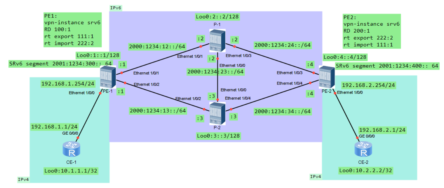
1.1 实验拓扑
1.2 地址规划
| 设备 | 接口 | IP地址 | 备注 |
|---|---|---|---|
| CE-1 | GE 0/0/0 | 192.168.1.1/24 | |
| Loopback 0 | 10.1.1.1/32 | ||
| PE-1 | Ethernet 1/0/0 | 192.168.1.254/30 | 采用NE40设备 |
| Ethernet 1/0/1 | 2001: 1234:12::1/64 | ||
| Ethernet 1/0/2 | 2001: 1234:13::1/64 | ||
| Loopback 0 | 1::1/128 | ||
| P-1 | Ethernet 1/0/0 | 2001: 1234:23::2/64 | 采用NE40设备 |
| Ethernet 1/0/1 | 2001: 1234:12::2/64 | ||
| Ethernet 1/0/3 | 2001: 1234:24::2/64 | ||
| Loopback 0 | 2::2/128 | ||
| P-2 | Ethernet 1/0/0 | 2001: 1234:23::3/64 | 采用NE40设备 |
| Ethernet 1/0/2 | 2001: 1234:13::3/64 | ||
| Ethernet 1/0/4 | 2001: 1234:34::3/64 | ||
| Loopback 0 | 3::3/128 | ||
| PE-2 | Ethernet 1/0/0 | 192.168.2.254/24 | 采用NE40设备 |
| Ethernet 1/0/3 | 2001: 1234:24::4/64 | ||
| Ethernet 1/0/4 | 2001: 1234:34::4/64 | ||
| Loopback 0 | 4::4/128 | ||
| CE-2 | GE 0/0/0 | 192.168.2.1/24 |
1.3 实验需求
某网络规划如上述拓扑图所示,当前网络需要部署SRv6-BE,作为负责该网络的网络工程师,请根据需求完成项目部署。
- 根据IP规划表完成路由设备上的接口IP配置(已预配)
- 使用OSPF协议实现CE和PE设备之间的OSPF邻接关系,并将10.1.1.1/32和10.2.2.2/32路由传递给PE(注:PE设备采用VPN实例创建OSPF进程)
- 在骨干网PE-1、P1、P2、PE-2之间部署ISIS协议,确保骨干网IPv6可以正常通信即可
- 在PE设备之间部署BGP4+,确保两边BGP4+邻居关系正常建立
- 在骨干网上以SRv6-BE方式部署SRv6
- 测试CE设备之间的连通性,对SRv6-BE的最短路径进行验证
- 对比SRv6-BE网络部署和SR-MPLS BE网络部署的差异性(可对比理论及命令的差别)
2 实验配置
配置流程规划:
-
检查预配置的ipv4&v6地址, 并测试连通性
回顾一下ipv6地址配置:
ipv6 enable int g0/0/1 ipv6 enable ipv6 address 2000:1234:12:: /64 link-local qu -
CE与PE之间配置OSPF
- 创建VRF并指定RT和RD
- 给接口绑定vpn实例(记得补回原来的地址)
- 创建VPN实例的OSPF
-
骨干网配置ISIS
- 设备配置isis地址、is-level、开销类型:宽模式
- 接口开启ipv6, 并启用isis ipv6模式
-
骨干网配置BGP4+及vpnv4
-
骨干网配置SRv6 BE
- 开启segment-routing srv6
- 配置当前设备srv6使用的源地址
- 按照拓扑信息配置locator信息
- IGP协议内引用locator信息
- bgp-vpnv4调用segment-routing
- 开启segment-routing srv6
-
配置流量转发路径
2.1 CE与PE之间配置VRF和OSPF
PE-1
ip vpn-instance srv6
	route-disting 100:1
		vpn-target 111:1 export
		vpn-target 222:2 import
		qu
	qu
int ethe 1/0/0
	ip binding vpn-instance srv6
	ip add 192.168.1.254 24
	qu
ospf 1 vpn-instance srv6
	area 0
		network 192.168.1.254 0.0.0.0
		qu
	qu
PE-2
ip vpn-instance srv6
	route-disting 100:2
		vpn-target 222:2 export
		vpn-target 111:1 import
		qu
	qu
int ethe 1/0/0
	ip binding vpn-instance srv6
	ip add 192.168.2.254 24
	qu
ospf 1 vpn-instance srv6
	area 0
		network 192.168.2.254 0.0.0.0
		qu
	qu
CE-1
ospf 1
	area 0
		network 192.168.1.1 0.0.0.0
		qu
	qu
CE-2
ospf 1
	area 0
		network 192.168.2.1 0.0.0.0
		qu
	qu
查看VPN实例接口配置情况
dis ip vpn-instance verbose srv6
2.2 PE与P之间配置ISIS、BGP4+的VPNv4
PE-1
isis 1
	network-entity 47.0001.0000.0000.0001.00
	is-level level-2
	cost-style wide
	ipv6 enable
	qu
int ethe 1/0/1
	ipv6 enable
	isis ipv6 enable
	qu
int ethe 1/0/2
	ipv6 enable
	isis ipv6 enable
	qu
int loop0
	ipv6 enable
	isis ipv6 enable
	qu

bgp 65001
	router-id 1.1.1.1
	group srv6
	peer srv6 connect-interface loop0
	peer srv6 next-hop-local
	peer srv6 as-number 65001
	peer 2::2 group srv6
	peer 3::3 group srv6
	peer 4::4 group srv6
	ipv4-family vpnv4
		peer 2::2 enable
		y
		peer 3::3 enable
		y
		peer 4::4 enable
		y
		qu
	ipv4-family vpn-instance srv6
		import ospf 1
		qu
	qu

ospf 1
	import-route bgp
	qu
P-1
isis 1
	network-entity 47.0001.0000.0000.0002.00
	is-level level-2
	cost-style wide
	ipv6 enable
	qu
int ethe 1/0/0
	ipv6 enable
	isis ipv6 enable
	qu
int ethe 1/0/1
	ipv6 enable
	isis ipv6 enable
	qu
int ethe 1/0/3
	ipv6 enable
	isis ipv6 enable
	qu
int loop0
	ipv6 enable
	isis ipv6 enable
	qu

bgp 65001
	router-id 2.2.2.2
	group srv6
	peer srv6 connect-interface loop0
	peer srv6 next-hop-local
	peer srv6 as-number 65001
	peer 3::3 group srv6
	peer 4::4 group srv6
	peer 1::1 group srv6
	ipv4-family vpnv4
		peer 3::3 enable
		y
		peer 4::4 enable
		y
		peer 1::1 enable
		y
		qu
	qu
P-2
isis 1
	network-entity 47.0001.0000.0000.0003.00
	is-level level-2
	cost-style wide
	ipv6 enable
	qu
int ethe 1/0/0
	ipv6 enable
	isis ipv6 enable
	qu
int ethe 1/0/2
	ipv6 enable
	isis ipv6 enable
	qu
int ethe 1/0/4
	ipv6 enable
	isis ipv6 enable
	qu
int loop0
	ipv6 enable
	isis ipv6 enable
	qu

bgp 65001
	router-id 3.3.3.3
	group srv6
	peer srv6 connect-interface loop0
	peer srv6 next-hop-local
	peer srv6 as-number 65001
	peer 2::2 group srv6
	peer 4::4 group srv6
	peer 1::1 group srv6
	ipv4-family vpnv4
		peer 2::2 enable
		y
		peer 4::4 enable
		y
		peer 1::1 enable
		y
		qu
	qu
PE-2
isis 1
	network-entity 47.0001.0000.0000.0004.00
	is-level level-2
	cost-style wide
	ipv6 enable
	qu
int ethe 1/0/3
	ipv6 enable
	isis ipv6 enable
	qu
int ethe 1/0/4
	ipv6 enable
	isis ipv6 enable
	qu
int loop0
	ipv6 enable
	isis ipv6 enable
	qu

bgp 65001
	router-id 4.4.4.4
	group srv6
	peer srv6 connect-interface loop0
	peer srv6 next-hop-local
	peer srv6 as-number 65001
	peer 2::2 group srv6
	peer 3::3 group srv6
	peer 1::1 group srv6
	ipv4-family vpnv4
		peer 2::2 enable
		y
		peer 3::3 enable
		y
		peer 1::1 enable
		y
		qu
	ipv4-family vpn-instance srv6
		import ospf 1
		qu
	qu

ospf 1
	import-route bgp
	qu
- PE设备isis如果修改为wide(默认为narrow模式), 当P设备未做同步修改时, isis的邻居将会正常建立, 但是无法传递路由
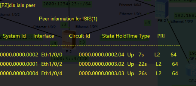
此时网络互联已完成, 可以通过查看isis/bgp邻居, 或是查看设备路由表来确保配置正确
dis isis peer
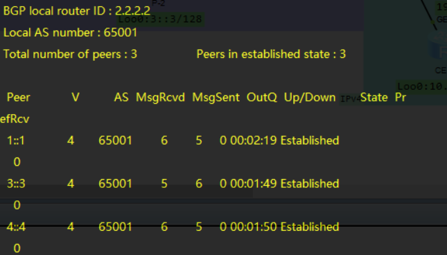
dis bgp vpnv4 all peer
dis bgp vpnv4 all routing
dis ipv6 routing-table
此时应观察到isis和bgp邻居都已成功建立
- 但此时两个site还未连通, 需要继续配置srv6
如果想建立BGP的ipv6邻居, 但因为MPLS VPN的网络架构中, 不需要用到单播地址簇的邻居关系(使用lsp连接), 所以不开启单播地址簇的邻居关系也没关系
bgp 65001
	ipv6-family unicast
		peer 4::4 enable
注: 虽然骨干网是ipv6, 但是的两个site是ipv4的路由信息, 因此需要使用BGP4+的vpnv4功能.
2.3 骨干网部署SRv6 BE
PE-1
segment-routing ipv6
	encapsulation source-address 1::1	#指定srv6的当前设备地址
	locator pe1 ipv6-prefix 2001:1234:100:: 64 static 32
		qu
	qu

isis 1
	segment-routing ipv6 locator pe1	#isis关联locator信息
	qu

bgp 65001
	ipv4-family vpnv4
		peer 4::4 prefix-sid
		qu
	ipv4-family vpn-instance srv6
		segment-routing ipv6 best-effort	#SRv6-BE
		segment-routing ipv6 locator pe1	#调用locator
		qu
	qu
PE-2
segment-routing ipv6
	encapsulation source-address 4::4
	locator pe2 ipv6-prefix 2001:1234:400:: 64
	qu

isis 1
	segment-routing ipv6 locator pe2
	qu

bgp 65001
	ipv4-family vpnv4
		peer 1::1 prefix-sid
		qu
	ipv4-family vpn-instance srv6
		segment-routing ipv6 best-effort
		segment-routing ipv6 locator pe2
		qu
	qu
PE-2这里没有预留静态function, 全动态分配, 这会导致无法手写opcode
查看当前设备srv6的locator信息
dis segment-routing ipv6 locator verbose
dis segment-routing ipv6 local-sid [end|end-x|end-dt4|end-dt6|dx4|dx6] forwarding #当前设备产生的各种SID
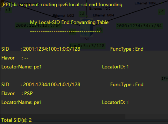
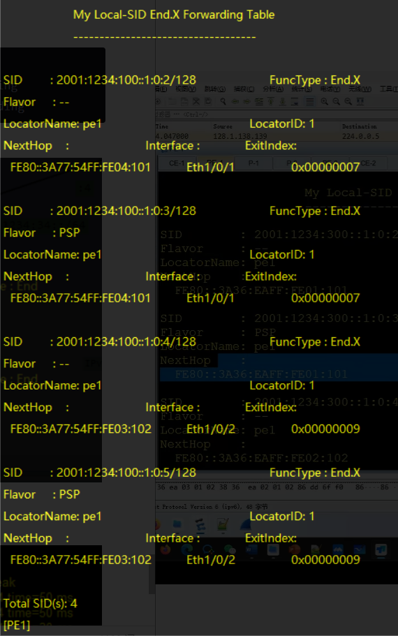
- 其中Flavor: PSP的含义为: 倒数第二跳弹出SRH头部
- local-sid中展示了PE-1到PE-2的最短路径, 有默认模式和倒数第二跳弹出模式
此时两端CE已经可以连通
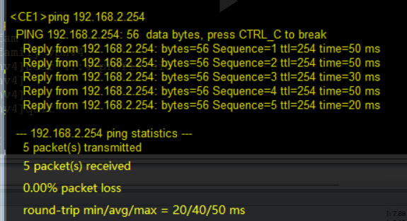
3 总结
3.1 参考文档
3.2 实验思考
-
对比SRv6-BE网络部署和SR-MPLS BE网络部署的差异性(可对比理论及命令的差别)
参考HCIE-广域承载解决方案专题实验01 SR-MPLS BE
-
理论方面:
-
SRv6在ipv6的扩展报头中使用SRH报头进行SRv6信息的传递与处理, 取代了SR-MPLS基于二层和三层之间的MPLS报头;
-
SRv6使用ipv6地址替代了SR-MPLS的标签栈作为转发的标签, 虽然都是使用SID List进行标签的存放, 但是不同于MPLS的标签弹出(pop)机制, SRv6使用SID Left来标明当前需要处理的SID信息, 只有在需要弹出SRH头部时才会随之一同丢弃;
-
SRv6支持Native IPv6, 可以无需全网部署SRv6, 只需在需要处理的节点配置SRv6即可, 而SR-MPLS需要在途径路径上都配置MPLS形成lsp路径.
-
segment分类上, SR-MPLS将其分为prefix SID、Adjacency SID以及Node SID, 而SRv6将其细分为END、END.X等对处理方式更加精准的segment
-
-
配置方面:
- 由于SRv6不再依赖MPLS标签进行转发, 因此整个实验都不会出现mpls相关配置
- segment-routing启用的是ipv6模式
- 无需指定tunnel隧道并配置隧道策略, 但是需要指定本地地址, 并在路由协议中关联Locator信息
-
-
为什么在完成了bgp和ospf的双向引入后, 在配置segment routing之前, 两端PE虽然通过BGP vpnv4学习到了对端CE的路由信息(存放在bgp vpnv4的路由表中), 两端PE的ospf lsdb中没有对端CE的路由信息?
虽然PE通过BGP学到了对端从OSPF中引入的CE路由信息, 但此时并没有生成PE之间的vpnv4信息转发路径, 因此对端CE的路由是不可达的, SR-MPLS中时通过MPLS的lsp来完成vpnv4流量转发, 但在SRv6中则需要指定好Locator并生成了SID之后才拥有转发vpnv4信息的能力, PE直到对端CE路由可达后才会下放到OSPF的lsdb中.