37款传感器与模块的提法,在网络上广泛流传,其实Arduino能够兼容的传感器模块肯定是不止37种的。鉴于本人手头积累了一些传感器和模块,依照实践出真知(一定要动手做)的理念,以学习和交流为目的,这里准备逐一动手试试做实验,不管成功与否,都会记录下来---小小的进步或是搞不定的问题,希望能够抛砖引玉。
【Arduino】108种传感器模块系列实验(资料+代码+图形+仿真)
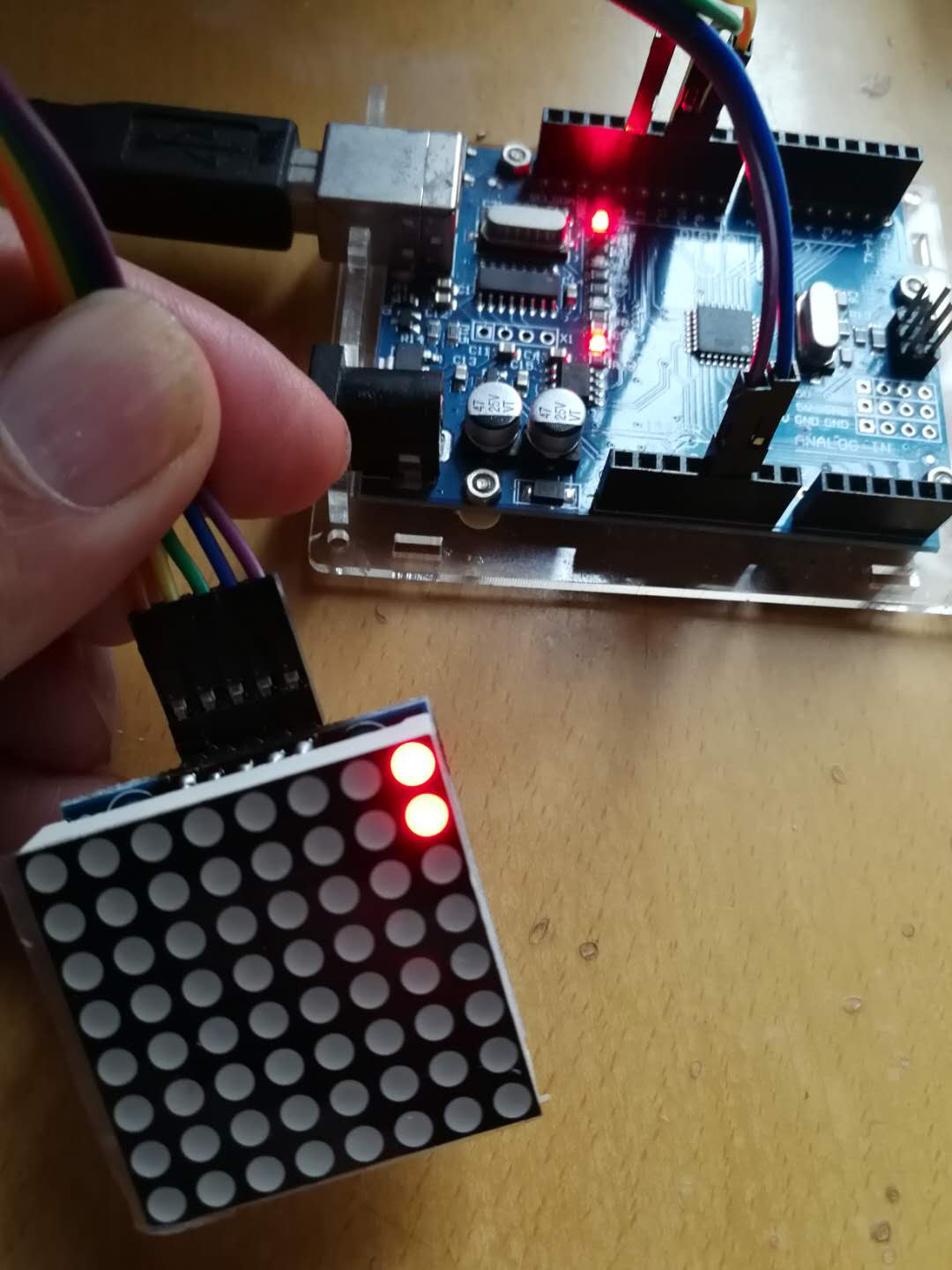
实验二十二:MAX7219点阵显示模块(8X8 LED共阴屏幕)
【Arduino】168种传感器模块系列实验(资料代码+仿真编程+图形编程)
实验二十二:MAX7219点阵显示模块(8X8 LED共阴)
项目之八:表情、箭和移动车交替模式
实验开源代码
/*
【Arduino】168种传感器模块系列实验(资料代码+仿真编程+图形编程)
实验二十二:MAX7219点阵显示模块(8X8 LED共阴)
项目之八:表情、箭和移动车交替模式
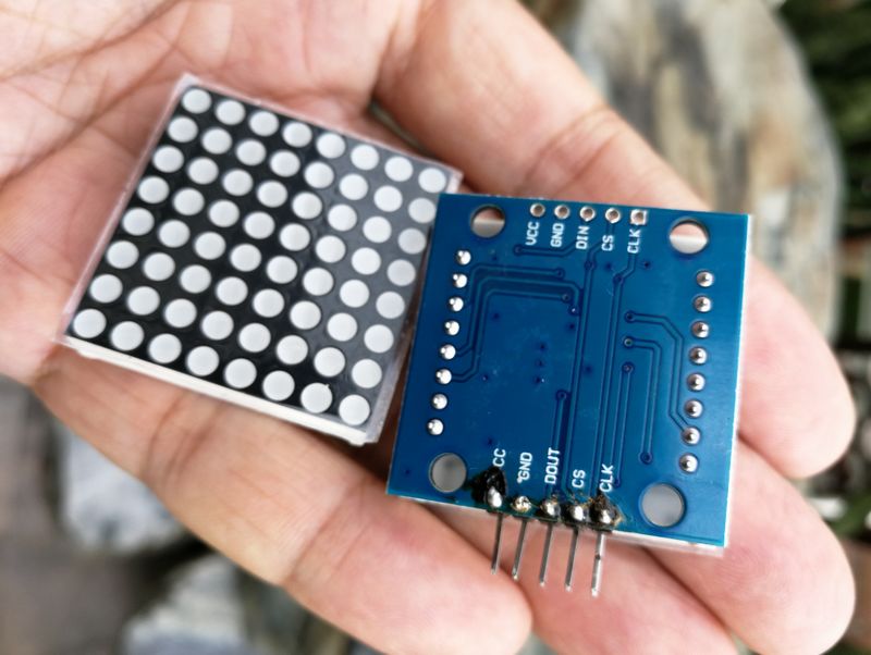
接脚连线:
MAX7219 UNO
VCC →→→→→ 5V
GND →→→→→ GND
DIN →→→→→ D12(数据)
CS →→→→→ D11(负载)
CLK →→→→→ D10(时钟)
*/
#include <LedControl.h>
int DIN = 12;
int CS = 11;
int CLK = 10;
LedControl lc = LedControl(DIN, CLK, CS, 0);
void setup() {
lc.shutdown(0, false);
lc.setIntensity(0, 10); //调整亮度最大为15
lc.clearDisplay(0);
}
void loop() {
//表情
byte smile[8] = {0x3C, 0x42, 0xA5, 0x81, 0xA5, 0x99, 0x42, 0x3C};
byte neutral[8] = {0x3C, 0x42, 0xA5, 0x81, 0xBD, 0x81, 0x42, 0x3C};
byte sad[8] = {0x3C, 0x42, 0xA5, 0x81, 0x99, 0xA5, 0x42, 0x3C};
//箭
byte arrow_up[8] = {0x18, 0x3C, 0x7E, 0xFF, 0x18, 0x18, 0x18, 0x18};
byte arrow_down[8] = {0x18, 0x18, 0x18, 0x18, 0xFF, 0x7E, 0x3C, 0x18};
//交替模式
byte d1[8] = {0xAA, 0x55, 0xAA, 0x55, 0xAA, 0x55, 0xAA, 0x55};
byte d2[8] = {0x55, 0xAA, 0x55, 0xAA, 0x55, 0xAA, 0x55, 0xAA};
//移动车
byte b1[8] = {0x00, 0x00, 0x00, 0x00, 0x18, 0x3C, 0x18, 0x3C}; //8*8LED点阵 取模软件生成
byte b2[8] = {0x00, 0x00, 0x00, 0x18, 0x3C, 0x18, 0x3C, 0x00};
byte b3[8] = {0x00, 0x00, 0x18, 0x3C, 0x18, 0x3C, 0x00, 0x00};
byte b4[8] = {0x00, 0x18, 0x3C, 0x18, 0x3C, 0x00, 0x00, 0x00};
byte b5[8] = {0x18, 0x3C, 0x18, 0x3C, 0x00, 0x00, 0x00, 0x00};
byte b6[8] = {0x3C, 0x18, 0x3C, 0x00, 0x00, 0x00, 0x00, 0x18};
byte b7[8] = {0x18, 0x3C, 0x00, 0x00, 0x00, 0x00, 0x18, 0x3C};
byte b8[8] = {0x3C, 0x00, 0x00, 0x00, 0x00, 0x18, 0x3C, 0x18};
//移动车
printByte(b1);
delay(50);
printByte(b2);
delay(50);
printByte(b3);
delay(50);
printByte(b4);
delay(50);
printByte(b5);
delay(50);
printByte(b6);
delay(50);
printByte(b7);
delay(50);
printByte(b8);
delay(50);
//交替模式
printByte(d1);
delay(300);
printByte(d2);
delay(300);
//箭
printByte(arrow_up);
delay(800);
printByte(arrow_down);
delay(500);
//表情
printByte(smile);
delay(500);
printByte(neutral);
delay(500);
printByte(sad);
delay(500);
}
void printByte(byte character []) {
int i = 0;
for (i = 0; i < 8; i++) {
lc.setRow(0, i, character[i]);
}
}
【Arduino】168种传感器模块系列实验(资料代码+仿真编程+图形编程)
实验二十二:MAX7219点阵显示模块(8X8 LED共阴)
项目之九:动态显示“Hello World”
实验开源程序
/*
  【Arduino】168种传感器模块系列实验(资料代码+仿真编程+图形编程)
  实验二十二:MAX7219点阵显示模块(8X8 LED共阴)
  项目之九:动态显示“Hello World”
  接脚连线:
  MAX7219       UNO
  VCC  →→→→→ 5V
  GND  →→→→→ GND
  DIN  →→→→→ D12(数据,数据接收引脚)
  CS   →→→→→ D11(负载,命令接收引脚)
  CLK  →→→→→ D10(时钟,时钟引脚)
*/

#include "LedControlMS.h"
#define NBR_MTX 2
LedControl lc=LedControl(12, 10, 11, NBR_MTX);

String sentence= "Hello World";
int letterCounter=0;
// 显示更新之间的等待时间
unsigned long delaytime=300;

void setup() { // 初始化并设置初始值。 声明函数设置
  // 显示模块在启动时处于省电模式
  Serial.begin(9600); //将数据速率设置为每秒 9600 位,以便与计算机进行串行数据通信
  Serial.println("Setup OK"); //将数据作为可读的文本打印到串行端口
  Serial.println("");
  Serial.println("Hello World!");
  letterCounter=0;

  for (int i=0; i< NBR_MTX; i++){
    lc.shutdown(i,false); //保持屏幕开启
    lc.setIntensity(i,8); // 将亮度设置为中等值
    lc.clearDisplay(i); // 清除每个字母后的显示
  }
}

void loop() { //声明函数循环
  char ch= sentence[letterCounter]; //定义字符串 ch
  letterCounter++;
  if (letterCounter>14) letterCounter=0; //设置循环
  lc.displayChar(0, lc.getCharArrayPosition(ch)); //在屏幕上显示每个字符
  delay(400);
  lc.clearAll();
  delay(300);
}
【Arduino】168种传感器模块系列实验(资料代码+仿真编程+图形编程)
实验二十二:MAX7219点阵显示模块(8X8 LED共阴)
项目之十:继续前行,往右箭头
实验开源代码
/*
  【Arduino】168种传感器模块系列实验(资料代码+仿真编程+图形编程)
  实验二十二:MAX7219点阵显示模块(8X8 LED共阴)
  项目之十:继续前行,往右箭头
  接脚连线:
  MAX7219       UNO
  VCC  →→→→→ 5V
  GND  →→→→→ GND
  DIN  →→→→→ D12(数据,数据接收引脚)
  CS   →→→→→ D11(负载,命令接收引脚)
  CLK  →→→→→ D10(时钟,时钟引脚)
*/

#include <LedControl.h>
LedControl display = LedControl(12,10,11,1);

const uint64_t R_IMAGES[] = {   //往右箭頭
  0x0000000100000000,
  0x0000010301000000,
  0x0001030703010000,
  0x0103070f07030100,
  0x02060f1f0f060200,
  0x040c1f3f1f0c0400,
  0x08183f7f3f180800,
  0x08183f7f3f180800,
  0x10307fff7f301000,
  0x2060fefefe602000,
  0x40c0fcfcfcc04000,
  0x8080f8f8f8808000,
  0x0000f0f0f0000000,
  0x0000e0e0e0000000,
  0x0000c0c0c0000000,
  0x0000808080000000,
  0x0000000000000000
};

const int R_IMAGES_LEN = sizeof(R_IMAGES)/8;

void setup(){
  display.clearDisplay(0);    // 清除螢幕
  display.shutdown(0, false);  // 關閉省電模式
  display.setIntensity(0, 10); // 設定亮度為 8 (介於0~15之間)
}

void displayImage(uint64_t image) {
  for (int i = 0; i < 8; i++) {
    byte row = (image >> i * 8) & 0xFF;
    for (int j = 0; j < 8; j++) {
      display.setLed(0, i, j, bitRead(row, j));
    }
  }
}

int i = 0;

void loop() {
   displayImage(R_IMAGES[i]);
  if (++i >= R_IMAGES_LEN ) {
    i = 0;
  }
  delay(100);
}


【Arduino】168种传感器模块系列实验(资料代码+仿真编程+图形编程)
实验二十二:MAX7219点阵显示模块(8X8 LED共阴)
项目之十一:制作一个随机电子骰子
实验开源代码
/*
  【Arduino】168种传感器模块系列实验(资料代码+仿真编程+图形编程)
  实验二十二:MAX7219点阵显示模块(8X8 LED共阴)
  项目之十一:制作一个随机电子骰子
  接脚连线:按钮开关接D3
  MAX7219       UNO
  VCC  →→→→→ 5V
  GND  →→→→→ GND
  DIN  →→→→→ D12(数据,数据接收引脚)
  CS   →→→→→ D11(负载,命令接收引脚)
  CLK  →→→→→ D10(时钟,时钟引脚)
*/

#include "LedControl.h"
LedControl lc=LedControl(12,10,11,1);

unsigned long delaytime=50;
int ButtonPin=3;
int Current=1;

void setup() {
lc.shutdown(0,false); //MAX72XX 在启动时处于省电模式,必须叫醒
lc.setIntensity(0,8); //将亮度设置为中等值
lc.clearDisplay(0); //并清除显示

randomSeed(analogRead(0));
pinMode(ButtonPin, INPUT);
}

void showNum(int x) {
//这里是字符的数据
byte one[8]={
B00000000,
B00000000,
B00000000,
B00111000,
B00111000,
B00000000,
B00000000,
B00000000};

byte two[8]={
B00000000,
B00000110,
B00000110,
B00000000,
B00000000,
B01100000,
B01100000,
B00000000};

byte three[8]={
B00000000,
B00111000,
B00111000,
B00000000,
B01100110,
B01100110,
B01100110,
B00000000};

byte four[8]={
B00000000,
B01100110,
B01100110,
B00000000,
B00000000,
B01100110,
B01100110,
B00000000};

byte five[8]={
B00000000,
B01100110,
B01100110,
B00011000,
B00011000,
B01100110,
B01100110,
B00000000};

byte six[8]={
B01100110,
B01100110,
B00000000,
B01100110,
B01100110,
B00000000,
B01100110,
B01100110};

switch (x) {
case 1:
lc.setRow(0,0,one[0]);
lc.setRow(0,1,one[1]);
lc.setRow(0,2,one[2]);
lc.setRow(0,3,one[3]);
lc.setRow(0,4,one[4]);
lc.setRow(0,5,one[5]);
lc.setRow(0,6,one[6]);
lc.setRow(0,7,one[7]);
break;

case 2:
lc.setRow(0,0,two[0]);
lc.setRow(0,1,two[1]);
lc.setRow(0,2,two[2]);
lc.setRow(0,3,two[3]);
lc.setRow(0,4,two[4]);
lc.setRow(0,5,two[5]);
lc.setRow(0,6,two[6]);
lc.setRow(0,7,two[7]);
break;

case 3:
lc.setRow(0,0,three[0]);
lc.setRow(0,1,three[1]);
lc.setRow(0,2,three[2]);
lc.setRow(0,3,three[3]);
lc.setRow(0,4,three[4]);
lc.setRow(0,5,three[5]);
lc.setRow(0,6,three[6]);
lc.setRow(0,7,three[7]);
break;

case 4:
lc.setRow(0,0,four[0]);
lc.setRow(0,1,four[1]);
lc.setRow(0,2,four[2]);
lc.setRow(0,3,four[3]);
lc.setRow(0,4,four[4]);
lc.setRow(0,5,four[5]);
lc.setRow(0,6,four[6]);
lc.setRow(0,7,four[7]);
break;
case 5:
lc.setRow(0,0,five[0]);
lc.setRow(0,1,five[1]);
lc.setRow(0,2,five[2]);
lc.setRow(0,3,five[3]);
lc.setRow(0,4,five[4]);
lc.setRow(0,5,five[5]);
lc.setRow(0,6,five[6]);
lc.setRow(0,7,five[7]);
break;

case 6:
lc.setRow(0,0,six[0]);
lc.setRow(0,1,six[1]);
lc.setRow(0,2,six[2]);
lc.setRow(0,3,six[3]);
lc.setRow(0,4,six[4]);
lc.setRow(0,5,six[5]);
lc.setRow(0,6,six[6]);
lc.setRow(0,7,six[7]);
break;
}
}

void loop() {
int Next;
boolean MarkStart=false; //标记是否按键抬起

if (digitalRead(ButtonPin)==LOW) {
showNum(Current);
do {
Next=random(1,7);
}

while (Current==Next); //因为如果两次出现相同的数字,看起来
//会觉得没有变,所以这里要保证生成不同
Current=Next;
delay(delaytime);
MarkStart=true;
}

if ((MarkStart==true) && (digitalRead(ButtonPin)==HIGH)){ //按键抬起,生成实际显示的结果
MarkStart=false;
showNum(random(1,7));
}
}

Arduino实验场景图