软件版本:vitis2021.1(vivado2021.1)
操作系统:WIN10 64bit
硬件平台:适用XILINX A7/K7/Z7/ZU/KU系列FPGA
登录"米联客"FPGA社区-www.uisrc.com视频课程、答疑解惑!
1概述
2 AXI4-Stream协议介绍
2.1信号定义
信号 | 源 | 描述 |
ACLK | 时钟源 | 信号在ACLK信号上升沿采样 |
ARESETn | 复位源 | 复位信号,ARESETn低电平有效 |
TVALID | master | TVALID代表主设备数据有效,当TVALID和TREADY同时有效完成数据收发 |
TREADY | slave | TREADY表示从设备准备可以,主设备可以发送数据,当TVALID和TREADY同时有效完成数据收发 |
TDATA[(8n-1):0] | master | TDATA axi-stream的数据 |
TSTRB[(n-1):0] | master | TSTRB[n-1:0]对应的bit位为1代表对应的字节有效,否则无效,但是会占用这个数据位。 |
TKEEP[(n-1):0] | master | KEEP[n-1:0]对应的bit位为1代表对应的字节有效,否则为空,可以丢掉。 |
TLAST | master | TLAST代表最后一个数据。 |
TID[(i-1):0] | master | TID是数据流的标识符,用来表明不同的数据流。 |
TDEST[(d-1):0] | master | TDEST为据流提供路由信息。 |
TUSER[(n-1):0] | master | TUSER一般用于数据的同步,代表stream数据的开始。 |
以上所有信号,在axi-stream传输中,不一定全部用到,具体根据应用场景的情况而定。
2.2 axi-stream方案展示
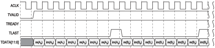

下图中是来自于xilinx vivado自带的axis_vid_out ip的视频输出时序。EOL就是tlast ,SOF就是tuser初次外还包括了VALID、READY、DATA信号。

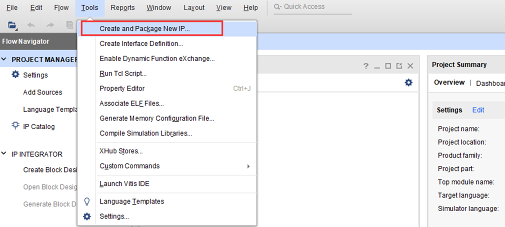
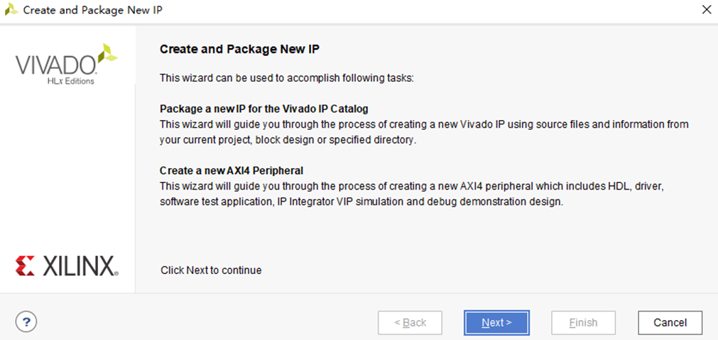
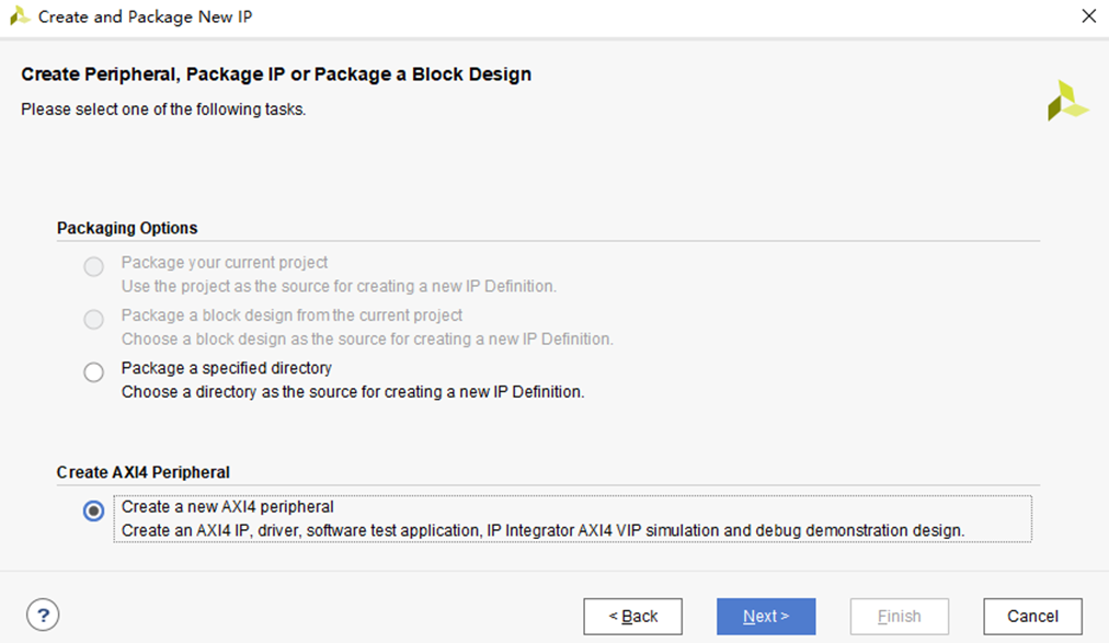
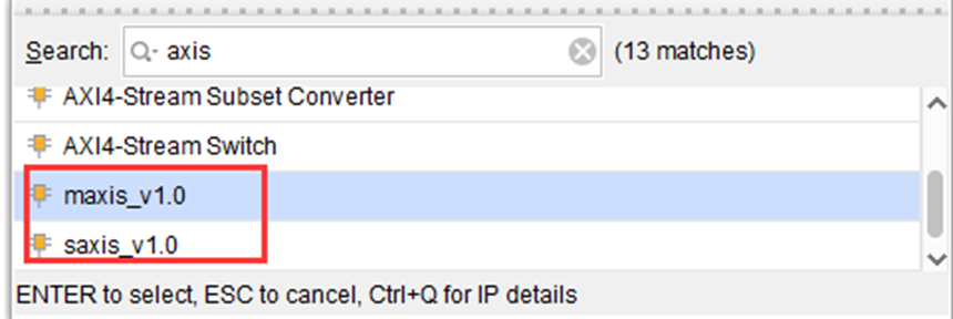
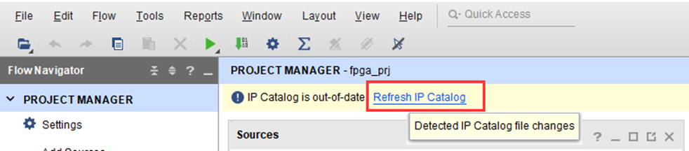
3创建axi-stream-slave总线接口IP
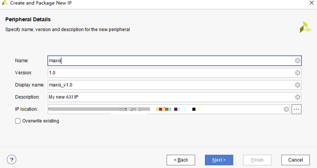

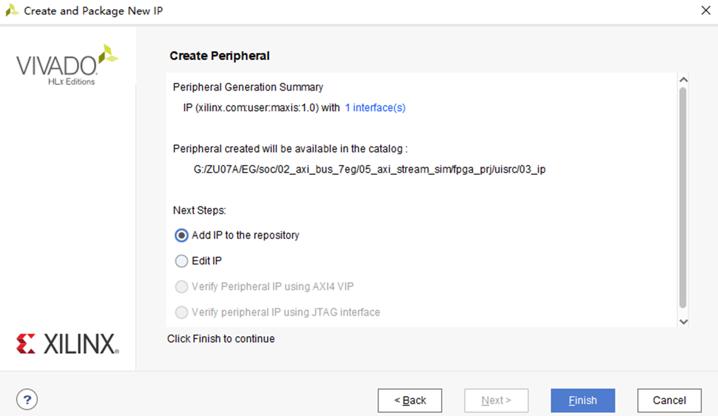
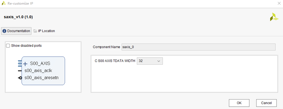
4创建axi-stream-master总线接口IP
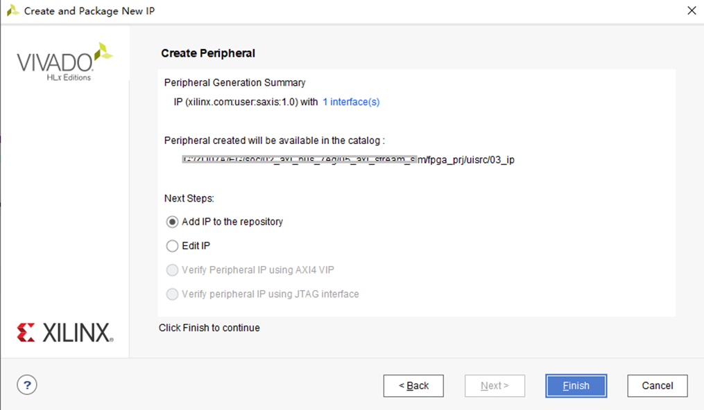
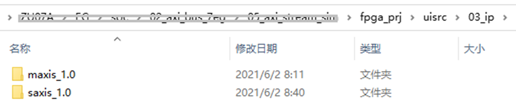
未来完成axi-steam协议的验证,采用以上方法,我们再创建一个saxis的IP


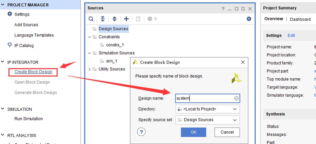
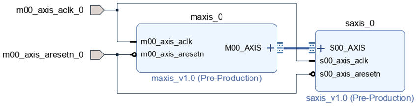
5创建FPGA图像化设计


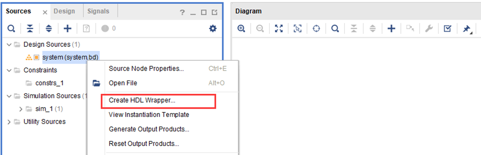
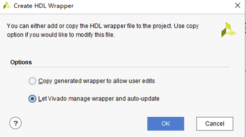
6创建仿真文件

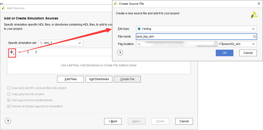

`timescale 1ns / 1ns module axis_top_sim(); reg m00_axis_aclk_0; reg m00_axis_aresetn_0; system_wrappertem system_wrapper_inst ( .m00_axis_aclk_0(m00_axis_aclk_0), .m00_axis_aresetn_0(m00_axis_aresetn_0) ); initial begin m00_axis_aclk_0 = 1'b0; m00_axis_aresetn_0 = 1'b0; #100; m00_axis_aresetn_0 = 1'b1; end always begin #5 m00_axis_aclk_0 = ~m00_axis_aclk_0; end endmodule |
7程序分析
`timescale 1 ns / 1 ps module maxis_v1_0_M00_AXIS # ( // Width of S_AXIS address bus. The slave accepts the read and write addresses of width C_M_AXIS_TDATA_WIDTH. parameter integer C_M_AXIS_TDATA_WIDTH = 32, // Start count is the number of clock cycles the master will wait before initiating/issuing any transaction. parameter integer C_M_START_COUNT = 32 ) ( // Global ports input wire M_AXIS_ACLK, // input wire M_AXIS_ARESETN, // Master Stream Ports. TVALID indicates that the master is driving a valid transfer, A transfer takes place when both TVALID and TREADY are asserted. output wire M_AXIS_TVALID, // TDATA is the primary payload that is used to provide the data that is passing across the interface from the master. output wire [C_M_AXIS_TDATA_WIDTH-1 : 0] M_AXIS_TDATA, // TSTRB is the byte qualifier that indicates whether the content of the associated byte of TDATA is processed as a data byte or a position byte. output wire [(C_M_AXIS_TDATA_WIDTH/8)-1 : 0] M_AXIS_TSTRB, // TLAST indicates the boundary of a packet. output wire M_AXIS_TLAST, // TREADY indicates that the slave can accept a transfer in the current cycle. input wire M_AXIS_TREADY ); // Total number of output data localparam NUMBER_OF_OUTPUT_WORDS = 8;
// function called clogb2 that returns an integer which has the // value of the ceiling of the log base 2. function integer clogb2 (input integer bit_depth); begin for(clogb2=0; bit_depth>0; clogb2=clogb2+1) bit_depth = bit_depth >> 1; end endfunction
// WAIT_COUNT_BITS is the width of the wait counter. localparam integer WAIT_COUNT_BITS = clogb2(C_M_START_COUNT-1);
// bit_num gives the minimum number of bits needed to address 'depth' size of FIFO. localparam bit_num = clogb2(NUMBER_OF_OUTPUT_WORDS);
// Define the states of state machine // The control state machine oversees the writing of input streaming data to the FIFO, // and outputs the streaming data from the FIFO parameter [1:0] IDLE = 2'b00, // This is the initial/idle state
INIT_COUNTER = 2'b01, // This state initializes the counter, once // the counter reaches C_M_START_COUNT count, // the state machine changes state to SEND_STREAM SEND_STREAM = 2'b10; // In this state the // stream data is output through M_AXIS_TDATA // State variable reg [1:0] mst_exec_state; // Example design FIFO read pointer reg [bit_num-1:0] read_pointer;
// AXI Stream internal signals //wait counter. The master waits for the user defined number of clock cycles before initiating a transfer. reg [WAIT_COUNT_BITS-1 : 0] count; //streaming data valid wire axis_tvalid; //Last of the streaming data wire axis_tlast; wire tx_en; //The master has issued all the streaming data stored in FIFO wire tx_done;
// I/O Connections assignments assign M_AXIS_TVALID = axis_tvalid; assign M_AXIS_TDATA = read_pointer; assign M_AXIS_TLAST = axis_tlast; assign M_AXIS_TSTRB = {(C_M_AXIS_TDATA_WIDTH/8){1'b1}};
// Control state machine implementation always @(posedge M_AXIS_ACLK) begin if (!M_AXIS_ARESETN) // Synchronous reset (active low) begin mst_exec_state <= IDLE; count <= 0; end else case (mst_exec_state) IDLE: mst_exec_state <= INIT_COUNTER: // The slave starts accepting tdata when // there tvalid is asserted to mark the // presence of valid streaming data if ( count == C_M_START_COUNT - 1 ) begin mst_exec_state <= SEND_STREAM; end else begin count <= count + 1; mst_exec_state <= INIT_COUNTER; end
SEND_STREAM: // The example design streaming master functionality starts // when the master drives output tdata from the FIFO and the slave // has finished storing the S_AXIS_TDATA if (tx_done) begin mst_exec_state <= IDLE; end else begin mst_exec_state <= SEND_STREAM; end endcase end
//tvalid generation //axis_tvalid is asserted when the control state machine's state is SEND_STREAM and //number of output streaming data is less than the NUMBER_OF_OUTPUT_WORDS. assign axis_tvalid = ((mst_exec_state == SEND_STREAM) && (read_pointer < NUMBER_OF_OUTPUT_WORDS));
// AXI tlast generation
assign axis_tlast = (read_pointer == NUMBER_OF_OUTPUT_WORDS - 1'b1)&& tx_en;
assign tx_done = axis_tlast;
//FIFO read enable generation
assign tx_en = M_AXIS_TREADY && axis_tvalid;
// Streaming output data is read from FIFO always @( posedge M_AXIS_ACLK ) begin if(!M_AXIS_ARESETN) begin read_pointer <= 0; end else if (tx_en) begin read_pointer <= read_pointer + 32'b1; end end
endmodule |
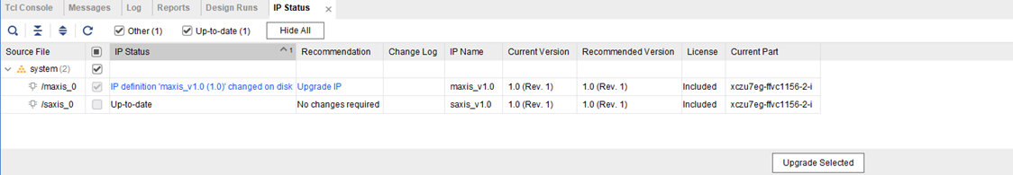
2:在Tcl Console中输入reset_project对工程IP复位

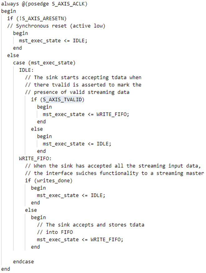
首先是状态机,当S_AXI_TVALID有效,saxis的状态机进入WRITE_FIFO

8实验结果
