SystemVerilog for Design Edition 2 Chapter 10
SystemVerilog extends the Verilog language with a powerful interface construct. Interfaces offer a new paradigm for modeling abstraction. The use of interfaces can simplify the task of modeling and verifying large, complex designs. This chapter contains a number of small examples, each one showing specific features of interfaces. These examples have been purposely kept relatively small and simple, in order to focus on specific features of interfaces. Chapter 11 then presents a larger example that uses interfaces in the context of a more complete design.
The concepts covered in this chapter are:
• Interface declarations
• Connecting interfaces to module ports
• Differences between interfaces and modules
• Interface ports and directions
• Tasks and functions in interfaces
• Using interface methods
• Procedural blocks in interfaces
• Parameterized interfaces
10.1 Interface concepts
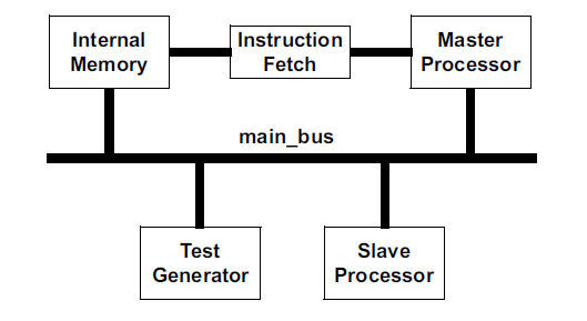
The Verilog language connects modules together through module ports. This is a detailed method of representing the connections between blocks of a design that maps directly to the physical connections that will be in the actual hardware. For large designs, however, using module ports to connect blocks of a design together can become tedious and redundant. Consider the following example that connects five blocks of a design together using a rudimentary bus architecture called main_bus, plus some additional connections between some of the design blocks. Figure 10-1 shows the block diagram for this simple design, and example 10-1 lists the Verilog source code for the module declarations involved.
Figure 10-1: Block diagram of a simple design
Example 10-1: Verilog module interconnections for a simple design
/********************** Top-level Netlist ********************/
module top (input wire clock, resetN, test_mode);
	wire [15:0] data, address, program_address, jump_address;
	wire [ 7:0] instruction, next_instruction;
	wire [ 3:0] slave_instruction;
	wire slave_request, slave_ready;
	wire bus_request, bus_grant;
	wire mem_read, mem_write;
	wire data_ready;

processor proc1 (
	// main_bus ports
	.data(data),
	.address(address),
	.slave_instruction(slave_instruction),
	.slave_request(slave_request),
	.bus_grant(bus_grant),
	.mem_read(mem_read),
	.mem_write(mem_write),
	.bus_request(bus_request),
	.slave_ready(slave_ready),
	// other ports
	.jump_address(jump_address),
	.instruction(instruction),
	.clock(clock),
	.resetN(resetN),
	.test_mode(test_mode)
);

slave slave1 (
	// main_bus ports
	.data(data),
	.address(address),
	.bus_request(bus_request),
	.slave_ready(slave_ready),
	.mem_read(mem_read),
	.mem_write(mem_write),
	.slave_instruction(slave_instruction),
	.slave_request(slave_request),
	.bus_grant(bus_grant),
	.data_ready(data_ready),
	// other ports
	.clock(clock),
	.resetN(resetN)
);

dual_port_ram ram (
	// main_bus ports
	.data(data),
	.data_ready(data_ready),
	.address(address),
	.mem_read(mem_read),
	.mem_write(mem_write),
	// other ports
	.program_address(program_address),
	.data_b(next_instruction)
);

test_generator test_gen(
	// main_bus ports
	.data(data),
	.address(address),
	.mem_read(mem_read),
	.mem_write(mem_write),
	// other ports
	.clock(clock),
	.resetN(resetN),
	.test_mode(test_mode)
);

instruction_reg ir (
	.program_address(program_address),
	.instruction(instruction),
	.jump_address(jump_address),
	.next_instruction(next_instruction),
	.clock(clock),
	.resetN(resetN)
);

endmodule

/********************* Module Definitions ********************/
module processor (
	// main_bus ports
	inout wire [15:0] data,
	output reg [15:0] address,
	output reg [ 3:0] slave_instruction,
	output reg slave_request,
	output reg bus_grant,
	output wire mem_read,
	output wire mem_write,
	input wire bus_request,
	input wire slave_ready,
	// other ports
	output reg [15:0] jump_address,
	input wire [ 7:0] instruction,
	input wire clock,
	input wire resetN,
	input wire test_mode
);
	... // module functionality code
endmodule

module slave (
	// main_bus ports
	inout wire [15:0] data,
	inout wire [15:0] address,
	output reg bus_request,
	output reg slave_ready,
	output wire mem_read,
	output wire mem_write,
	input wire [ 3:0] slave_instruction,
	input wire slave_request,
	input wire bus_grant,
	input wire data_ready,
	// other ports
	input wire clock,
	input wire resetN
);
	... // module functionality code
endmodule

module dual_port_ram (
	// main_bus ports
	inout wire [15:0] data,
	output wire data_ready,
	input wire [15:0] address,
	input tri0 mem_read,
	input tri0 mem_write,
	// other ports
	input wire [15:0] program_address,
	output reg [ 7:0] data_b
);
	... // module functionality code
endmodule

module test_generator (
	// main_bus ports
	output wire [15:0] data,
	output reg [15:0] address,
	output reg mem_read,
	output reg mem_write,
	// other ports
	input wire clock,
	input wire resetN,
	input wire test_mode
);
	... // module functionality code
endmodule

module instruction_reg (
	output reg [15:0] program_address,
	output reg [ 7:0] instruction,
	input wire [15:0] jump_address,
	input wire [ 7:0] next_instruction,
	input wire clock,
	input wire resetN
);
	... // module functionality code
endmodule
10.1.1 Disadvantages of Verilog’s module ports
Verilog’s module ports provide a simple and intuitive way of describing the interconnections between the blocks of a design. In large, complex designs, however, Verilog’s module ports have several shortcomings. Some of these are:
• Declarations must be duplicated in multiple modules.
• Communication protocols must be duplicated in several modules.
• There is a risk of mismatched declarations in different modules.
• A change in the design specification can require modifications in multiple modules.
connecting modules in a netlist requires redundant port declarations
One disadvantage of using Verilog’s module ports to connect major blocks of a design together is readily apparent in the example code above. The signals that make up main_bus in the preceding example must be declared in each module that uses the bus, as well as in the top-level netlist that connects the design together. In this simple example, there are only a handful of signals in main_bus, so the redundant declarations are mostly just an inconvenience. In a large, complex design, however, this redundancy becomes much more than an inconvenience. A large design could have dozens of modules connected to the same bus, with dozens of duplicated declarations in each module. If the ports of one module should
inadvertently be declared differently than the rest of the design, a functional error can occur that may be difficult to find.
The replicated port declarations also mean that, should the specification of the bus change during the design process, or in a next generation of the design, then each and every module that shares the bus must be changed. All netlists used to connect the modules using the bus must also be changed. This wide spread effect of a change is counter to good coding styles. One goal of coding is to structure the code in such a way that a small change in one place should not require changing other areas of the code. A weakness in the Verilog language is that a change to the ports in one module will usually require changes in other modules.
protocols must be duplicated in each module
Another disadvantage of Verilog’s module ports is that communication protocols must be duplicated in each module that utilize the interconnecting signals between modules. If, for example, three modules read and write from a shared memory device, then the read and write control logic must be duplicated in each of these modules.
module ports inhibit abstract top-down design
Yet another disadvantage of using module ports to connect the blocks of a design together is that detailed interconnections for the design must be determined very early in the design cycle. This is counter to the top-down design paradigm, where models are first written at an abstract level without extensive design detail. At an abstract level, an interconnecting bus should not require defining each and every signal that makes up the bus. Indeed, very early in the design specification, all that might be known is that the blocks
of the design will share certain information. In the block diagram shown in Figure 10-1 on page 264, the main_bus is represented as a single connection. Using Verilog’s module ports to connect the design blocks together, however, does not allow modeling at that same level of abstraction. Before any block of the design can be modeled, the bus must first be broken down to individual signals.
10.1.2 Advantages of SystemVerilog interfaces
an interface is an abstract port type
SystemVerilog adds a powerful new port type to Verilog, called an interface. An interface allows a number of signals to be grouped together and represented as a single port. The declarations of the signals that make up the interface are contained in a single location. Each module that uses these signals then has a single port of the interface type, instead of many ports with the discrete signals.
Example 10-2 shows how SystemVerilog’s interfaces can reduce the amount of code required to model the simple design shown in Figure 10-1. By encapsulating the signals that make up main_bus as an interface, the redundant declarations for these signals within each module are eliminated.
Example 10-2: SystemVerilog module interconnections using interfaces
/******************* Interface Definitions *******************/
interface main_bus;
	wire [15:0] data;
	wire [15:0] address;
	logic [ 7:0] slave_instruction;
	logic slave_request;
	logic bus_grant;
	logic bus_request;
	logic slave_ready;
	logic data_ready;
	logic mem_read;
	logic mem_write;
endinterface

/********************** Top-level Netlist ********************/
module top (input logic clock, resetN, test_mode);
	logic [15:0] program_address, jump_address;
	logic [ 7:0] instruction, next_instruction;

    main_bus bus ( ); // instance of an interface
					  // (instance name is bus)
processor proc1 (
	// main_bus ports
	.bus(bus), // interface connection
	// other ports
	.jump_address(jump_address),
	.instruction(instruction),
	.clock(clock),
	.resetN(resetN),
	.test_mode(test_mode)
);

slave slave1 (
	// main_bus ports
	.bus(bus), // interface connection
	// other ports
	.clock(clock),
	.resetN(resetN)
);

dual_port_ram ram (
	// main_bus ports
	.bus(bus), // interface connection
	// other ports
    .program_address(program_address),
	.data_b(next_instruction)
);

test_generator test_gen(
	// main_bus ports
	.bus(bus), // interface connection
	// other ports
	.clock(clock),
	.resetN(resetN),
	.test_mode(test_mode)
);

instruction_reg ir (
	.program_address(program_address),
	.instruction(instruction),
	.jump_address(jump_address),
	.next_instruction(next_instruction),
	.clock(clock),
	.resetN(resetN)
);

endmodule

/********************* Module Definitions ********************/
module processor (
	// main_bus interface port
	main_bus bus, // interface port
	// other ports
	output logic [15:0] jump_address,
	input logic [ 7:0] instruction,
	input logic clock,
	input logic resetN,
	input logic test_mode
);
	... // module functionality code
endmodule

module slave (
	// main_bus interface port
	main_bus bus, // interface port
	// other ports
	input logic clock,
	input logic resetN
);
	... // module functionality code
endmodule

module dual_port_ram (
	// main_bus interface port
	main_bus bus, // interface port
	// other ports
	input logic [15:0] program_address,
	output logic [ 7:0] data_b
);
	... // module functionality code
endmodule

module test_generator (
	// main_bus interface port
	main_bus bus, // interface port
	// other ports
	input logic clock,
	input logic resetN,
	input logic test_mode
);
	... // module functionality code
endmodule

module instruction_reg (
	output logic [15:0] program_address,
	output logic [ 7:0] instruction,
	input logic [15:0] jump_address,
	input logic [ 7:0] next_instruction,
	input logic clock,
	input logic resetN
);
	... // module functionality code
endmodule
In example 10-2, above, all the signals that are in common between the major blocks of the design have been encapsulated into a single location—the interface declaration called main_bus. The top-level module and all modules that make up these blocks do not repetitively declare these common signals. Instead, these modules simply use the interface as the connection between them.
Encapsulating common signals into a single location eliminates the redundant declarations of Verilog modules. Indeed, in the preceding example, since clock and resetN are also common to all modules, these signals could have also been brought into the interface. This further simplification is shown later in this chapter, in example 10-3 on page 274.
10.1.3 SystemVerilog interface contents
interfaces can contain functionality
SystemVerilog interfaces are far more than just a bundle of wires. Interfaces can encapsulate the full details of the communication between the blocks of a design. Using interfaces:
• The discrete signal and ports for communication can be defined in one location, the interface.
• Communication protocols can be defined in the interface.
• Protocol checking and other verification routines can be built directly into the interface.
interfaces eliminate redundant declarations
With Verilog, the communication details must be duplicated in each module that shares a bus or other communication architecture. SystemVerilog allows all the information about a communication architecture and the usage of the architecture to be defined in a single, common location. An interface can contain type declarations, tasks, functions, procedural blocks, program blocks, and assertions. SystemVerilog interfaces also allow multiple views of the interface to be defined. For example, for each module connected to the interface, the data_bus signal can be defined to be an input, output or bidirectional port.
All of these capabilities of SystemVerilog interfaces are described in more detail in the following sections of this chapter.
10.1.4 Differences between modules and interfaces
Interfaces are not the same as modules
There are three fundamental differences that make an interface differ from a module. First, an interface cannot contain design hierarchy. Unlike a module, an interface cannot contain instances of modules or primitives that would create a new level of implementation hierarchy. Second, an interface can be used as a module port, which is what allows interfaces to represent communication channels between modules. It is illegal to use a module in a port list. Third, an interface can contain modports, which allow each module connected to the interface to see the interface differently. Modports are described in detail in section 10.6 on page 281.
10.2 Interface declarations
interfaces are defined in a similar way as modules
Syntactically, the definition of an interface is very similar to the definition of a module. An interface can have ports, just as a module does. This allows signals that are external to the interface, such as a clock or reset line, to be brought into the interface and become part of the bundle of signals represented by the interface. Interfaces can also contain declarations of any Verilog or SystemVerilog type, including all variable types, all net types and user-defined types.
Example 10-3 shows a definition for an interface called main_bus, with three external signals coming into the interface: clock, resetN and test_mode. These external signals can now be connected to each module through the interface, without having to explicitly connect the signals to each module.
Notice in this example how the instance of interface main_bus has the clock, resetN and test_mode signals connected to it, using the same syntax as connecting signals to an instance of a module.
Example 10-3: The interface definition for main_bus, with external inputs
/******************* Interface Definitions *******************/
interface main_bus (input logic clock, resetN, test_mode);
	wire [15:0] data;
	wire [15:0] address;
	logic [ 7:0] slave_instruction;
	logic slave_request;
	logic bus_grant;
	logic bus_request;
	logic slave_ready;
	logic data_ready;
	logic mem_read;
	logic mem_write;
endinterface

/********************** Top-level Netlist ********************/
module top (input logic clock, resetN, test_mode);
	logic [15:0] program_address, jump_address;
	logic [ 7:0] instruction, next_instruction;

main_bus bus ( // instance of an interface
	.clock(clock),
	.resetN(resetN),
	.test_mode(test_mode)
);

processor proc1 (
	// main_bus ports
	.bus(bus), // interface connection
	// other ports
	.jump_address(jump_address),
	.instruction(instruction)
);
...

/*** remainder of netlist and module definitions are not ***/
/*** listed — they are similar to example 10-2, but ***/
/*** clock and resetN do not need to be passed to each ***/
/*** module instance as discrete ports. ***/
interface instances can use .name and .* connections
The SystemVerilog simplified port connection styles of .name and .* can also be used with interface port connections. These constructs are covered in section 9.4 on page 233. The previous examples can be made even more concise by combining the use of interfaces with the use of .* port connections. This is illustrated in example 10-4, which follows.
Example 10-4: Using interfaces with .* connections to simplify complex netlists
/******************* Interface Definitions *******************/
interface main_bus (input logic clock, resetN, test_mode);
	wire [15:0] data;
	wire [15:0] address;
	logic [ 7:0] slave_instruction;
	logic slave_request;
	logic bus_grant;
	logic bus_request;
	logic slave_ready;
	logic data_ready;
	logic mem_read;
	logic mem_write;
endinterface

/********************** Top-level Netlist ********************/
module top (input logic clock, resetN, test_mode);
	logic [15:0] program_address, jump_address;
	logic [ 7:0] instruction, next_instruction, data_b;

	main_bus bus ( .* );
	processor proc1 ( .* );
	slave slave1 ( .* );
	instruction_reg ir ( .* );
	test_generator test_gen ( .* );
	dual_port_ram ram ( .*, .data_b(next_instruction) );
endmodule

/*** remainder of netlist and module definitions are not ***/
/*** listed — they are similar to example 10-2, but ***/
/*** clock and resetN do not need to be passed to each ***/
/*** module instance as discrete ports.
SystemVerilog greatly simplifies netlists
In the Verilog version of this simple example, which was listed in example 10-1 on page 264, the top-level netlist, module top, required 65 lines of code, excluding blank lines and comments. Using SystemVerilog interfaces along with .*, example 10-4, above, requires just 10 lines of code, excluding blank lines and comments, to model the same connectivity.
10.2.1 Source code declaration order
an interface name can be used before its definition
The name of an interface can be referenced in two contexts: in a port of a module, and in an instance of the interface. Interfaces can be used as module ports without concern for file order dependencies. Just as with modules, the name of an interface can be referenced before the source code containing the interface definition has been read in by the software tool. This means any module can use an interface as a module port, without concern for the order in which the source code is compiled.
10.2.2 Global and local interface definitions
interfaces can be global declarations
An interface can be defined separately from module definitions, using the keywords interface and endinterface. The name of the interface will be in the global module definition name scope, just as with module names. This allows an interface definition to be used as a port by any module, anywhere in the design hierarchy.
interfaces can be limited to specific hierarchy scopes
An interface definition can be nested within a module, making the name of the interface local to that module. Only the containing module can instantiate a locally declared interface. This allows the use of an interface to be limited to just one portion of the design hierarchy, such as to just within an IP model.
10.3 Using interfaces as module ports
With SystemVerilog, a port of a module can be declared as an interface type, instead of the Verilog input, output or inout port directions.
10.3.1 Explicitly named interface ports
a module port can be the name of an interface
A module port can be explicitly declared as a specific type of interface. This is done by using the name of an interface as the port type. The syntax is:
module <module_name> (<interface_name> <port_name>);
For example:
interface chip_bus;
	...
endinterface

module CACHE (chip_bus pins, // interface port
			  input clock);
	...
endmodule
An explicitly named interface port can only be connected to an interface of the same name. An error will occur if any other interface definition is connected to the port. Explicitly named interface ports ensure that a wrong interface can never be inadvertently connected to the port. Explicitly naming the interface type that can be connected to the port also serves to document directly within the port declaration exactly how the port is intended to be used.
10.3.2 Generic interface ports
a port can be declared using the interface keyword
A generic interface port defines the port type using the keyword interface, instead of a using the name of a specific interface type. The syntax is:
module <module_name> (interface <port_name>);
When the module is instantiated, any interface can be connected to the generic interface port. This provides flexibility in that the same module can be used in multiple ways, with different interfaces connected to the module. In the following example, module RAM is defined with a generic interface port:
module RAM (interface pins,
			input clock);
	...
endmodule
10.3.3 Synthesis guidelines
Both styles of connecting an interface to a module are synthesizable.
10.4 Instantiating and connecting interfaces
interfaces are instantiated the same way as modules
An instance of an interface is connected to a port of a module instance using a port connection, just as a discrete net would be connected to a port of a module instance. This requires that both the interface and the modules to which it is connected be instantiated.
The syntax for an interface instance is the same as for a module instance. If the definition of the interface has ports, then signals can be connected to the interface instance, using either the port order connection style or the named port connection style, just as with a module instance.
Interface connection rules
NOTE: It is illegal to leave an interface port unconnected.
interface ports must be connected
A module input, output or inout port can be left unconnected on a module instance. This is not the case for an interface port. A port that is declared as an interface, whether generic or explicit, must be connected to an interface instance or another interface port. An error will occur if an interface port is left unconnected.
On a module instance, a port that has been declared as an interface type must be connected to an interface instance, or another interface port that is higher up in the hierarchy. If a port declaration has an
explicitly named interface type, then it must be connected to an interface instance of the identical type. If a port declaration has a generic interface type, then it can be connected to an interface instance of any type.
The SystemVerilog .name and .* port connection styles can also be used with interface instances, as is illustrated in example 10-4 on page 275. These port connection styles are discussed in section 9.4 on page 233.
Interfaces connected to interface instances
the port of an interface can connect to another interface
A port of an interface can also be defined as an interface. This capability allows one interface to be connected to another interface. The main bus of a design, for example might have one or more sub-busses. Both the main bus and its sub-busses can be modeled as interfaces. The sub-bus interfaces can be represented as ports of the main interface.
10.5 Referencing signals within an interface
signals in an interface are referenced using the port name
Within a module that has an interface port, the signals inside the interface must be accessed using the port name, using the following syntax:
<port_name>.<internal_interface_signal_name>
In example 10-3 on page 274, the interface definition for main_bus contains declarations for clock and resetN. Module slave has an interface port, with the port name of bus. The slave model can access the clock variable within the interface by referencing it as bus.clock. For example:
always @(posedge bus.clock, negedge bus.resetN)
	...
Example 10-5 lists partial code for module slave. The model contains several references to signals within the main_bus interface.
Example 10-5: Referencing signals within an interface
module slave (
// main_bus interface port
main_bus bus
// other ports
);
// internal signals
logic [15:0] slave_data, slave_address;
logic [15:0] operand_A, operand_B;
logic mem_select, read, write;
assign bus.address = mem_select? slave_address: ’z;
assign bus.data = bus.slave_ready? slave_data: ’z;

enum logic [4:0] {RESET = 5'b00001,
				  START = 5'b00010,
				  REQ_DATA = 5'b00100,
				  EXECUTE = 5'b01000,
				  DONE = 5'b10000} State, NextState;

always_ff @(posedge bus.clock, negedge bus.resetN) begin: FSM
	if (!bus.resetN) State <= START;
	else State <= NextState;
end

always_comb begin : FSM_decode
	unique case (State)
		START: if (!bus.slave_request) begin
					bus.bus_request = 0;
					NextState = State;
				end
				else begin
					operand_A = bus.data;
					slave_address = bus.address;
					bus.bus_request = 1;
					NextState = REQ_DATA;
				end
			... // decode other states
		endcase
	end: FSM_decode
endmodule
TIP: Use short names for the names of interface ports.
Since signals within an interface are accessed by prepending the interface port name to the signal name, it is convenient to use short names for interface port names. This keeps the reference to the interface signal name short and easy to read. The names within the interface can be descriptive and meaningful, as within any Verilog module.
10.6 Interface modports
Interfaces provide a practical and straightforward way to simplify connections between modules. However, each module connected to an interface may need to see a slightly different view of the connections within the interface. For example, to a slave on a bus, an interrupt_request signal might be an output from the slave, whereas to a processor on the same bus, interrupt_request would be an input.
modports define interface connections from the perspective of the module
SystemVerilog interfaces provide a means to define different views of the interface signals that each module sees on its interface port. The definition is made within the interface, using the modport keyword.
Modport is an abbreviation for module port. A modport definition describes the module ports that are represented by the interface. An interface can have any number of modport definitions, each describing how one or more other modules view the signals within the interface.
A modport defines the port direction that the module sees for the signals in the interface. Examples of two modport declarations are:
interface chip_bus (input logic clock, resetN);
	logic interrupt_request, grant, ready;
	logic [31:0] address;
	wire [63:0] data;

modport master (input interrupt_request,
				input address,
				output grant, ready,
				inout data,
				input clock, resetN);

modport slave (output interrupt_request,
			   output address,
			   input grant, ready,
			   inout data,
			   input clock, resetN);
endinterface
The modport definitions do not contain vector sizes or types. This information is defined as part of the signal type declarations in the interface. The modport declaration only defines whether the connecting
module sees a signal as an input, output, bidirectional inout, or ref port.
10.6.1 Specifying which modport view to use
SystemVerilog provides two methods for specifying which modport view a module interface port should use:
• As part of the interface connection to a module instance
• As part of the module port declaration in the module definition
Both of these specification styles are synthesizable.
Selecting the modport in the module instance
the modport can be selected in the module instance
When a module is instantiated and an instance of an interface is connected to a module instance port, the specific modport of the interface can be specified. The connection to the modport is specified as:
<interface_instance_name>.<modport_name>
For example:
chip_bus bus; // instance of an interface
primary i1 (bus.master); // use master modport
The following code snippet illustrates connecting two modules together with an interface called chip_bus. The module called primary is connected to the master view of the interface, and the module called secondary is connected to the slave view of the same interface:
Example 10-6: Selecting which modport to use at the module instance
interface chip_bus (input logic clock, resetN);
	modport master (...);
	modport slave (...);
endinterface

module primary (interface pins); // generic interface port
	...
endmodule

module secondary (chip_bus pins); // specific interface port
	...
endmodule

module chip (input logic clock, resetN);
	chip_bus bus (clock, resetN); // instance of an interface
	primary i1 (bus.master); // use the master modport view
	secondary i2 (bus.slave); // use the slave modport view
endmodule
When the modport to be used is specified in the module instance, the module definition can use either a generic interface port type or an explicitly named interface port type, as discussed in sections 10.3.2 on page 278, and 10.3.1 on page 277. The preceding example shows a generic interface port definition for primary module, and an explicitly named port type for secondary module.
Selecting the modport in the module port declaration
the modport can be selected in the module definition
The specific modport of an interface to be used can be specified directly as part of the module port declaration. The modport to be connected to the interface is specified as:
<interface_name>.<modport_name>
For example:
module secondary (chip_bus.slave pins);
	...
endmodule
The explicit interface name must be specified in the port type when the modport to be used is specified as part of the module definition. The instance of the module simply connects an instance of the interface to the module port, without specifying the name of a modport.
The following code snippet shows a more complete context of specifying which modport is to be connected to a module, as part of the definition of the module.
Example 10-7: Selecting which modport to use at the module definition
interface chip_bus (input logic clock, resetN);
	modport master (...);
	modport slave (...);
endinterface

module primary (chip_bus.master pins); // use master modport
	...
endmodule

module secondary (chip_bus.slave pins); // use slave modport
	...
endmodule

module chip (input logic clock, resetN);
	chip_bus bus (clock, resetN); // instance of an interface
	primary i1 (bus); // will use the master modport view
	secondary i2 (bus); // will use the slave modport view
endmodule
NOTE: A modport can be selected in either the module instance or the module definition, but not both.
The modport view that a module is to use can only be specified in one place, either on the module instance or as part of the module definition. It is an error to select which modport is to be used in both places.
Connecting to interfaces without specifying a modport
when no modport is used, nets are bidirectional, and variables are references
Even when an interface is defined with modports, modules can still be connected to the complete interface, without specifying a specific modport. However, the port directions of signals within an interface are only defined as part of a modport view. When no modport is specified as part of the connection to the interface, all nets in the interface are assumed to have a bidirectional inout direction, and all variables in the interface are assumed to be of type ref. A ref port passes values by reference, rather than by copy. This allows the module to access the variable in the interface, rather than a copy of the variable. Module reference ports are covered in section 9.7 on page 255.
Synthesis considerations
Synthesis supports both styles of specifying which modport is to be used with a module. Most synthesis compilers will expand the interface port of a module into the individual ports represented in the modport definition. The following code snippets show the preand post-synthesis module definitions of a module using an interface with modports.
Pre-synthesis model, with an interface port:
module primary (chip_bus.master pins);
	...
endmodule

interface chip_bus (input wire clock, resetN);
logic interrupt_request, grant, ready;
logic [31:0] address;
wire [63:0] data;

modport master (input interrupt_request,
				input address,
				output grant, ready,
				inout data,
				input clock, resetN);
endinterface
Post-synthesis model:
module primary (interrupt_request, address,
grant, ready, data,
clock, resetN);
input interrupt_request,
input [31:0] address,
output grant, ready,
inout [63:0] data,
input clock, resetN);
... // synthesized model functionality
endmodule
Synthesis compilers might create different names for the separate ports than those shown in the example above.
If no modport is specified when the model is synthesized, then all signals within the interface become bidirectional inout ports on the synthesized module.
10.6.2 Using modports to define different sets of connections
In a more complex interface between several different modules, it may be that not every module needs to see the same set of signals within the interface. Modports make it possible to create a customized view of the interface for each module connected.
Restricting module access to interface signals
modports limit access to the contents of an interface
A module can only directly access the signals listed in its modport definition. This makes it possible to have some signals within the interface completely hidden from view to certain modules. For example, the interface might contain a net called test_clock that is only used by modules connected to the interface through the master modport, and not by modules connected through the slave modport.
A modport does not prohibit the use of a full hierarchy path to access any object in an interface. However, full hierarchy paths are not synthesizable, and are primarily used for verification.
It is also possible to have internal signals within an interface that are not visible through any of the modport views. These internal signals might be used by protocol checkers or other functionality contained within the interface, as discussed later in this chapter. If a module is connected to the interface without specifying a modport, the module will have access to all signals defined in the interface.
Example 10-8 adds modports to the main_bus interface example. The processor module, the slave module and the RAM module all use different modports within the main_bus interface, and the signals within the interface that can be accessed by each of these modules are different. The test block is connected to the main_bus without specifying a modport, giving the test block complete, unrestricted access to all signals within the interface.
Example 10-8: A simple design using an interface with modports
/******************* Interface Definitions *******************/
interface main_bus (input logic clock, resetN, test_mode);
	wire [15:0] data;
	wire [15:0] address;
	logic [ 7:0] slave_instruction;
	logic slave_request;
	logic bus_grant;
	logic bus_request;
	logic slave_ready;
	logic data_ready;
	logic mem_read;
	logic mem_write;

modport master (inout data,
				output address,
				output slave_instruction,
				output slave_request,
				output bus_grant,
				output mem_read,
				output mem_write,
				input bus_request,
				input slave_ready,
				input data_ready,
				input clock,
				input resetN,
				input test_mode
);

modport slave (inout data,
			   inout address,
			   output mem_read,
			   output mem_write,
			   output bus_request,
			   output slave_ready,
			   input slave_instruction,
			   input slave_request,
			   input bus_grant,
			   input data_ready,
			   input clock,
			   input resetN
);

modport mem (inout data,
			 output data_ready,
			 input address,
			 input mem_read,
			 input mem_write
);

endinterface

/********************** Top-level Netlist ********************/
module top (input logic clock, resetN, test_mode);
	logic [15:0] program_address, jump_address;
	logic [ 7:0] instruction, next_instruction, data_b;

	main_bus bus ( .* ); // instance of an interface
	processor proc1 (.bus(bus.master), .* );
	slave slave1 (.bus(bus.slave), .* );
	instruction_reg ir ( .* );
	test_generator test_gen (.bus(bus), .* );
	dual_port_ram ram (.bus(bus.mem), .* ,
						.data_b(next_instruction) );
endmodule

/*** remainder of netlist and module definitions are not ***/
/*** listed — they are similar to example 10-2, but ***/
/*** clock and resetN do not need to be passed to each ***/
/*** module instance as discrete ports. ***/
10.7 Using tasks and functions in interfaces
interfaces can contain functionality
Interfaces can encapsulate the full details of the communication protocol between modules. For instance, the main_bus protocol in the previous example includes handshaking signals between the master processor and the slave processor. In regular Verilog, the master processor module would need to contain the procedural code to assert and de-assert its handshake signals at the appropriate time, and to monitor the slave handshake inputs. Conversely, the slave processor would need to contain the procedural code to assert and de-assert its handshake signals, and to monitor the handshake inputs coming from the master processor or the RAM.
Describing the bus protocol within each module that uses a bus leads to duplicated code. If any change needs to be made to the bus protocol, the code for the protocol must be changed in each and every module that shares the bus.
10.7.1 Interface methods
an interface method is a task or function
SystemVerilog allows tasks and functions to be declared within an interface. These tasks and functions are referred to as interface methods. A task or function that is defined within an interface is written using the same syntax as if it had been within a module, and can contain the same types of statements as within a module. These interface methods can operate on any signals within the interface. Values can be passed in to interface methods from outside the interface as input arguments. Values can be written back from interface methods as output arguments or function returns.
methods encapsulate functionality in one place
Interface methods offer several advantages for modeling large designs. Using interface methods, the details of communication from one module to another can be moved to the interface. The code for communicating between modules does not need to be replicated in each module. Instead, the code is only written once, as interface methods, and shared by each module connected using the interface. Within each module, the interface methods are called, instead of implementing the communication protocol functionality within the module. Thus, an interface can be used not only to encapsulate the data connecting modules, but also the communication protocols between the modules.
10.7.2 Importing interface methods
modules can import interface methods
If the interface is connected via a modport, the method must be specified using the import keyword. The import definition is specified within the interface, as part of a modport definition. Modports specify interface information from the perspective of the module. Hence, an import declaration within a modport indicates that the module is importing the task or function.
The import declaration can be used in two ways:
• Import using just the task or function name
• Import using a full prototype of the task or function
Import using a task or function name
a method can be imported using just its name
The simplest form of importing a task or function is to simply specify the name of the task or function. The basic syntax is:
modport ( import <task_function_name> );
An example of using this style is:
modport in (import Read,
			import parity_gen,
			input clock, resetN );
Import using a task or function prototype
a method can be imported using a full prototype
The second style of an import declaration is to specify a full prototype of the task or function arguments. This style requires that the keyword task or function follow the import keyword. It also requires that the task or function name be followed by a set of parentheses, which contain the formal arguments of the task or funciton. The basic syntax of this style of import declarations is:
modport (import task <task_name>(<task_formal_arguments) );
modport (import function <function_name> (<formal_args>) );
For example:
modport in (import task Read
		   (input [63:0] data,
	  output [31:0] address),

import function parity_gen
			(input [63:0] data),
	  input clock, resetN);
A full prototype can serve to document the arguments of the task or function directly as part of the modport declaration. This additional code documentation can be convenient if the actual task or function
is defined in a package, and therefore the definition is not in the package source code for easy visual reference.
The full prototype is required when the task or function has been exported from another module (explained in section 10.7.4 on page 293), or when a function has been externally defined using System- Verilog’s Direct Programming Interface (not covered in this book).
Calling imported interface methods
imported methods are accessed using the port name
Importing a task or function through a modport gives the module using the modport access to the interface method. The task or function is called by prepending the interface port name to the task or
function name, the same as when a signal within an interface is accessed.
<interface_port_name>.<method_name>
Alternate methods within interfaces
interfaces can contain alternate methods
Modports provide a way to use different methods and protocols within the same interface. The interface can contain a variety of different methods, each using different protocols or types.
The following code snippet example illustrates an interface called math_bus. Within the interface, different read methods are defined, which retrieve either integer data or floating point data through an interface. Two modules are defined, called integer_math_unit and floating_point_unit, both of which use the same math_bus interface. Each module will access different types of information, based on the modport used in the instantiation of the module.
Example 10-9: Using modports to select alternate methods within an interface
interface math_bus (input logic clock, resetN);
	int a_int, b_int, result_int;
	real a_real, b_real, result_real;
	...

task IntegerRead (output int a_int, b_int);
	... // do handshaking to fetch a and b values
endtask

task FloatingPointRead (output real a_real, b_real);
	... // do handshaking to fetch a and b values
endtask

modport int_io (import IntegerRead,
				input clock, resetN,
				output result_int);

modport fp_io (import FloatingPointRead,
			   input clock, resetN,
			   output result_real);
endinterface

/********************** Top-level Netlist ********************/
module dual_mu (input logic clock, resetN);
	math_bus bus_a (clock, resetN); // 1st instance of interface
	math_bus bus_b (clock, resetN); // 2nd instance of interface
	integer_math_unit i1 (bus_a.int_io);
	// connect to interface using integer types
	floating_point_unit i2 (bus_b.fp_io);
	// connect to interface using real types
endmodule

/********************* Module Definitions ********************/
module integer_math_unit (interface io);
	int a_reg, b_reg;
	always @(posedge io.clock)
		begin
			io.IntegerRead(a_reg, b_reg); // call method interface
			... // process math operation
		end
endmodule

module floating_point_unit (interface io);
	real a_reg, b_reg;
	always @(posedge io.clock)
		begin
			io.FloatingPointRead(a_reg, b_reg); // call method in interface
			... // process math operation
		end
endmodule
10.7.3 Synthesis guidelines for interface methods
Modules that use tasks or functions imported from interfaces are synthesizable. Synthesis will infer a local copy of the imported task or function within the module. The post-synthesis version of the module will contain the logic of the task or functions; it will no longer look to the interface for that functionality.
NOTE: Imported tasks or functions must be declared as automatic and not contain static declarations in order to be synthesized.
An automatic task or function allocates new storage each time it is called. When a module calls an imported task or function, a new copy is allocated. This allows synthesis to treat the task or function as if were a local copy within the module.
10.7.4 Exporting tasks and functions
modules can export methods into an interface
SystemVerilog interfaces and modports provide a mechanism to define a task or function in one module, and then export the task or function through an interface to other modules.
NOTE: Exporting tasks and functions is not synthesizable.
exported methods are not synthesizable
Exporting tasks or functions into an interface is not synthesizable. This modeling style should be reserved for abstract models that are not intended to be synthesized.
An export declaration in an interface modport does not require a full prototype of the task or function arguments. Only the task or function name needs to be listed in the modport declaration.
If an exported task or function has default values for any of its formal arguments, then each import declaration of the task or function must have a complete prototype of the task/function arguments. A full prototype for the import declaration is also required if the task or function call uses named argument passing instead of passing by position.
The code fragments in example 10-10 show a function called check that is declared in module CPU. The function is exported from the CPU through the master modport of the chip_bus interface. The same function is imported into any modules that use the slave modport of the interface. To any module connected to the slave modport, the check function appears to be part of the interface, just like any other function imported from an interface. Modules using the slave modport do not need to know the actual
location of the check function definition.
Example 10-10: Exporting a function from a module through an interface modport
interface chip_bus (input logic clock, resetN);
	logic request, grant, ready;
	logic [63:0] address, data;

	modport master (output request, ...
					export check );

	modport slave (input request, ...
				   import check );
endinterface

module CPU (chip_bus.master io);
	function check (input parity, input [63:0] data);
		...
	endfunction
	...
endmodule
Exporting a task or function to the entire interface
The export declaration allows a module to export a task or function to an interface through a specific modport of the interface. A task or function can also be exported to an interface without using a modport. This is done by declaring an extern prototype of the task or function within the interface. For example:
Example 10-11: Exporting a function from a module into an interface
interface chip_bus (input logic clock, resetN);
logic request, grant, ready;
logic [63:0] address, data;

extern function check(input logic parity,
					  input logic [63:0] data);

modport master (output request, ...);

modport slave (input request, ...
	import function check
		(input logic parity,
		input logic [63:0] data) );
endinterface

module CPU (chip_bus.master io);
function check (input logic parity, input logic [63:0] data);
	...
endfunction
...
endmodule
Restrictions on exporting tasks and functions
NOTE: It is illegal to export the same function name from multiple instances of a module. It is legal, however, to export a task name from multiple instances, using an extern forkjoin declaration.
restrictions on exporting functions
SystemVerilog places a restriction on exporting functions through interfaces. It is illegal to export the same function name from two different modules, or two instances of the same module, into the same interface. For example, module A and module B cannot both export a function called check into the same interface.
restrictions on exporting tasks
SystemVerilog places a restriction on exporting tasks through interfaces.
It is illegal to export the same task name from two different
modules, or two instances of the same module, into the same interface,
unless an extern forkjoin declaration is used. The multiple
export of a task corresponds to a multiple response to a
broadcast. Tasks can execute concurrently, each taking a different
amount of time to execute statements, and each call returning different
values through its outputs. The concurrent response of modules
A and B containing a call to a task called task1 is conceptually modeled by:
fork
	<hierarchical_name_of_module_A>.task1(q, r);
	<hierarchical_name_of_module_B>.task1(q, r);
join
extern forkjoin allows multiple instances of exported tasks
Because an interface should not contain the hierarchical names of the modules to which it is connected, the task is declared as extern forkjoin, which infers the behavior of the fork...join block above. If the task contains outputs, it is the last instance of the task to finish that determines the final output value.
This construct can be useful for abstract, non-synthesizable transaction level models of busses that have slaves, where each slave determines its own response to broadcast signals (see example 12-2 on page 335 for an example). The extern forkjoin can also be used for configuration purposes, such as counting the number of modules connected to an interface. Each module would export the same task, name which increments a counter in the interface.
10.8 Using procedural blocks in interfaces
interfaces can contain protocol checkers and other functionality
In addition to methods (tasks and functions), interfaces can contain Verilog procedural blocks and continuous assignments. This allows an interface to contain functionality that can be described using
always, always_comb, always_ff, always_latch, initial or final procedural blocks, and assign statements. An interface can also contain verification program blocks.
One usage of procedural blocks within interfaces is to facilitate verification of a design. One application of using procedural statements within an interface is to build protocol checkers into the interface. Each time modules pass values through the interface, the built-in protocol checkers can verify that the design protocols are being met. Examples of using procedural code within interfaces are presented in the companion book, SystemVerilog for Verification1.
10.9 Reconfigurable interfaces
Interfaces can use parameter redefinition and generate statements, in the same way as modules. This allows interface models to be defined that can be reconfigured each time an interface is instantiated.
Parameterized interfaces
interfaces can use parameters, the same as modules
Parameters can be used in interfaces to make vector sizes and other declarations within the interface reconfigurable using Verilog’s parameter redefinition constructs. SystemVerilog also adds the ability to parameterize types, which is covered in section 9.9 on page 260.
Example 10-12, below, adds parameters to example 10-9 on page 291 shown earlier, which uses different modports to pass either integer data or real data through the same interface. In this example, the variable types of the interface are parameterized, so that each instance of the interface can be configured to use integer or real types.
Example 10-12: Using parameters in an interface
interface math_bus #(parameter type DTYPE = int)
					(input logic clock);
	DTYPE a, b, result; // parameterized types
	...
	task Read (output DTYPE a, b);
		... // do handshaking to fetch a and b values
	endtask

	modport int_io (import Read,
					input clock,
					output result);

	modport fp_io (import Read,
				   input clock,
				   output result);
endinterface

module top (input logic clock, resetN);
	math_bus bus_a(clock); // use int data
	math_bus (#.DTYPE(real)) bus_b(clock); // use real data
	integer_math_unit i1 (bus_a.int_io);
		// connect to interface using integer types
	floating_point_unit i2 (bus_b.fp_io);
		// connect to interface using real types
endmodule // end of module top
The preceding example uses the Verilog-2001 style for declaring parameters within a module and for parameter redefinition. The older Verilog-1995 style of declaring parameters and doing parameter redefinition can also be used with interfaces.
Using generate blocks
interfaces can use generate blocks
The Verilog-2001 generate statement can also be used to create reconfigurable interfaces. Generate blocks can be used to replicate continuous assignment statements or procedural blocks within an interface any number of times.
10.10 Verification with interfaces
Using only Verilog-style module ports, without interfaces, a typical design and verification paradigm is to develop and test each module of a design, independent of other modules in the design. After each module is independently verified, the modules are connected together to test the communication between modules. If there is a problem with the communication protocols, it may be necessary to make design changes to multiple modules.
communication protocols can be verified before a design is modeled
Interfaces enable a different paradigm for verification. With interfaces, the communication channels can be developed as interfaces independently from other modules. Since an interface can contain methods for the communication protocols, the interface can be tested and verified independent of the rest of the design. Modules that use the interface can be written knowing that the communication between modules has already been verified.
Verification of designs that use interfaces is covered in much greater detail in the companion book, SystemVerilog for Verification1.
10.11 Summary
This chapter has presented one of more powerful additions to the Verilog language for modeling very large designs: interfaces. An interface encapsulates the communication between major blocks of a design. Using interfaces, the detailed and redundant module port and netlist declarations are greatly simplified. The details are moved to one modeling block, where they are defined once, instead of in many different modules. An interface can be defined globally, so it can be used by any module anywhere in the design hierarchy. An interface can also be defined to be local to one hierarchy scope, so that only that scope can use the interface.
Interfaces do more than provide a way to bundle signals together. The interface modport definition provides a simple yet powerful way to customize the interface for each module that it is connected
to. The ability to incorporate methods (tasks and functions) and procedural code within an interface make it possible instrument and drive the simulation model in one convenient location.
- SystemVerilog Chapter Edition Design forsystemverilog chapter edition design systemverilog catalog edition design solutions edition chapter primer systemverilog systemverilog接口 systemverilog第一次logic 数组systemverilog systemverilog randomization dynamic array systemverilog模板vscode systemverilog xilinx vivado 2020