SystemVerilog for Design Edition 2 Chapter 6
The Verilog language provides a general purpose procedural block, called always, that is used to model a variety of hardware types as well as verification routines. Because of the general purpose application of the always procedural block, the design intent is not readily apparent.
SystemVerilog extends Verilog by adding hardware type-specific procedural blocks that clearly indicate the designer’s intent. By reducing the ambiguity of the general purpose always procedural block, simulation, synthesis, formal checkers, lint checkers, and other EDA software tools can perform their tasks with greater accuracy, and with greater consistency between different tools.
SystemVerilog also provides a number of enhancements to Verilog tasks and functions. Some of these enhancements make the Verilog HDL easier to use, and others substantially increase the power of using tasks and functions for modeling large, complex designs.
The topics covered in this chapter include:
• Combinational logic procedural blocks
• Latched logic procedural blocks
• Sequential logic procedural blocks
• Task and function enhancements
6.1 Verilog general purpose always procedural block
an always procedural block is an infinite loop
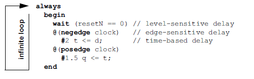
The Verilog always procedural block is an infinite loop that repeatedly executes the statements within the loop. In order for simulation time to advance, the loop must contain some type of time control or event control. This can be in the form of a fixed delay, represented with the # token, a delay until an expression evaluates as true, represented with the wait keyword, or a delay until an expression changes value, represented with the @ token. Verilog’s general purpose always procedural block can contain any number of time controls or event controls, and the controls can be specified anywhere within the procedural block.
The following example illustrates using these time and event controls. The example is syntactically correct, but does not follow proper synthesis modeling guidelines.
Sensitivity lists
an edge event control can be used as a sensitivity list
An edge sensitive event control at the very beginning of an always procedural block is typically referred to as the sensitivity list for that procedural block. Since no statement within the procedural block can execute until the edge-sensitive event control is satisfied, the entire block is sensitive to changes on the signals listed in the event control. In the following example, the execution of statements in the procedural block are sensitive to changes on a and b.
always @(a, b) // sensitivity list
	begin
		sum = a + b;
		diff = a - b;
		prod = a * b;
	end
General purpose usage of always procedural blocks
always can represent any type of logic
The Verilog always procedural block is used for general purpose modeling. At the RTL level, the always procedural block can be used to model combinatorial logic (often referred to as combinational logic), latched logic, and sequential logic. At more abstract modeling levels, an always procedural block can be used to model algorithmic logic behavior without clearly representing the implementation details of that behavior, such as an implicit state machine that performs a number of operations on data over multiple clock cycles. The same general purpose always procedural block is also used in testbenches to model clock oscillators and other verification tasks that need to be repeated throughout the verification process.
Inferring implementation from always procedural blocks
tools must infer design intent from the procedural block’s contents
The multi-function role of the general purpose always procedural block places a substantial burden on software tools such as synthesis compilers and formal verification. It is not enough for these types of tools to execute the statements within the procedural block. Synthesis compilers and formal verification tools must also try to deduce what type of hardware is being represented—combinational, latched or sequential logic. In order to infer the proper type of hardware implementation, synthesis compilers and formal tools must examine the statements and event controls within the procedural block.
The following always procedural block is syntactically correct, but is not synthesizable. The procedural block will compile and simulate without any compilation or run-time errors, but a synthesis compiler or formal verification tool would probably have errors, because the functionality within does not clearly indicate whether the designer was trying to model combinational, sequential or latched logic.
always @(posedge clock) begin
	wait (!resetN)
	if (mode) q1 = a + b;
	else q1 = a - b;
		q2 <= q1 | (q2 << 2);
		q2++;
	end
In order to determine how the behavior of this example can be realized in hardware, synthesis compilers and formal tools must examine the behavior of the code logic, and determine exactly when each statement will be executed and when each variable will be updated. A few, but not all, of the factors these tools must consider are:
• What type of hardware can be inferred from the sensitivity list?
• What can be inferred from if...else and case decisions?
• What can be inferred from assignment statements and the operators within those statements?
• Is every variable written to by this procedural block updated in each loop of the always procedural block? That is, is there any implied storage within the procedural block’s functionality that would infer latched behavior?
• Are there assignments in the procedural block that never actually update the variable on the left-side? (In the preceding example the q2++ statement will never actually increment q2, because the line before is a nonblocking assignment that updates its left-hand side, which is q2, after the ++ operation).
• Could other procedural blocks elsewhere in the same module affect the variables being written into by this procedural block?
synthesis guidelines for always procedural blocks
In order to reduce the ambiguity of what hardware should be inferred from the general purpose always procedural block, synthesis compilers place a number of restrictions and guidelines on the usage of always blocks. The rules for synthesis are covered in the IEEE 1364.1 standard for Verilog Register Transfer Level Synthesis1. Some highlights of these restrictions and guidelines are:
combinational logic
To represent combinational logic with a general purpose always procedural block:
• The always keyword must be followed by an edge-sensitive event control (the @ token).
• The sensitivity list of the event control cannot contain posedge or negedge qualifiers.
• The sensitivity list should include all inputs to the procedural block. Inputs are any signal read by the procedural block, where that signal receives its value from outside the procedural block.
• The procedural block cannot contain any other event controls.
• All variables written to by the procedural block must be updated for all possible input conditions.
• Any variables written to by the procedural block cannot be written to by any other procedural block
latched logic
To represent latched logic with a general purpose always procedural block:
• The always keyword must be followed by an edge-sensitive event control (the @ token).
• The sensitivity list of the event control cannot contain posedge or negedge qualifiers.
• The sensitivity list should include all inputs to the procedural block. Inputs are any signal read by the procedural block, where that signal receives its value from outside the procedural block.
• The procedural block cannot contain any other event controls.
• At least one variable written to by the procedural block must not be updated for some input conditions.
• Any variables written to by the procedural block cannot be written to by any other procedural block.
sequential logic
To represent sequential logic with a general purpose always procedural block:
• The always keyword must be followed by an edge-sensitive event control (the @ token).
• All signals in the event control sensitivity list must be qualified with posedge or negedge qualifiers.
• The procedural block cannot contain any other event controls.
• Any variables written to by the procedural block cannot be written to by any other procedural block.
modeling guidelines cannot be enforced for a general purpose procedural block
Since Verilog always procedural blocks are general purpose procedural blocks, these synthesis guidelines cannot be enforced other by software tools. Simulation tools, for example, must allow always procedural blocks to be used in a variety of ways, and not just within the context imposed by synthesis compilers. Because simulation and synthesis are not enforcing the same semantic rules for always procedural blocks, mismatches in simulation and synthesis results can occur if the designer does not follow strict, self-imposed modeling guidelines. Formal verification tools may also require that self-imposed modeling guidelines be followed, to prevent mismatches in simulation results and formal verification results.
6.2 SystemVerilog specialized procedural blocks
SystemVerilog adds three specialized procedural blocks to reduce the ambiguity of the Verilog general purpose always procedural block when modeling hardware. These are: always_comb, always_latch and always_ff.
specialized procedural blocks are synthesizable
These specialized procedural blocks are infinite loops, the same as an always procedural block. However, the procedural blocks add syntactic and semantic rules that enforce a modeling style compatible with the IEEE 1364.1 synthesis standard. These specialized procedural blocks are used to model synthesizable RTL logic.
The specialized always_comb, always_latch and always_ff procedural blocks indicate the design intent. Software tools do not need to infer from context what the designer intended, as must be done with the general purpose always procedural block. If the content of a specialized procedural block does not match the rules for that type of logic, software tools can issue warning messages.
specific procedural block types document design intent
By using always_comb, always_latch, and always_ff procedural blocks, the engineer’s intent is clearly documented for both software tools and for other engineers who review or maintain the model. Note, however, that SystemVerilog does not require software tools to verify that a procedural block’s contents match the type of logic specified with the specific type of always procedural block. Warning messages regarding the procedural block’s contents are optional.
6.2.1 Combinational logic procedural blocks
always_comb represents combinational logic
The always_comb procedural block is used to indicate the intent to model combinational logic.
always_comb
	if (!mode)
		y = a + b;
	else
		y = a - b;
always_comb infers its sensitivity list
Unlike the general purpose always procedural block, it is not necessary to specify a sensitivity list with always_comb. A combinational logic sensitivity list can be automatically inferred, because software tools know that the intent is to represent combinational logic. This inferred sensitivity list includes every signal that is read by the procedural block, if the signal receives its value from outside the procedural block. Temporary variables that are only assigned values using blocking assignments, and are only read within the procedural block, are not included in the sensitivity list. SystemVerilog also includes in the sensitivity list any signals read by functions called from the procedural block, except for temporary variables that are only assigned and read within the function. The rules for inferring the sensitivity of bit selects, part selects and array indexing are described in the SystemVerilog LRM.
Because the semantic rules for always_comb are standardized, all software tools will infer the same sensitivity list. This eliminates the risk of mismatches that can occur with a general purpose always procedural block, should the designer inadvertently specify an incorrect sensitivity list.
shared variables are prohibited
The always_comb procedural block also requires that variables on the left-hand side of assignments cannot be written to by any other procedural block. This restriction prevents a form of shared variable usage that does not behave like combinational logic. The restriction matches the guidelines for synthesis, and ensures that all software tools—not just synthesis—are enforcing the same modeling rules.
Non-ambiguous design intent
tools do not need to infer design intent
An important advantage of always_comb over the general purpose always procedural block is that when always_comb is specified, the designer’s intent is clearly stated. Software tools no longer need to examine the contents of the procedural block to try to infer what type of logic the engineer intended to model. Instead, with the intent of the procedural block explicitly stated, software tools can examine the contents of the procedural block and issue warning messages if the contents do not represent combinational logic.
In the following example with a general purpose always procedural block, a software tool cannot know what type of logic the designer intended to represent, and consequently will infer that latched logic was intended, instead of combinational logic.
always @(a, en)
	if (en) y = a;
With SystemVerilog, this same example could be written as follows:
always_comb
	if (en) y = a;
Software tools can then tell from the always_comb keyword that the designer’s intent was to model combinational logic, and can issue a warning that a latch would be required to realize the procedural block’s functionality in hardware.
The correct way to model the example above as combinational logic would be to include an else branch so that the output y would be updated for all conditions of en. If the intent were that y did not change when en was false, then the correct way to model the logic would be to use an always_latch procedural block, as
described in section 6.2.2 on page 150 of this chapter.
Checking that the content matches the type of procedural block is optional in the IEEE SystemVerilog standard. Some software tools, such as lint checkers and synthesis compilers will most likely perform these optional checks. Other tools, such as simulators, might not perform these checks.
Automatic evaluation at time zero
always_comb ensures outputs start off consistent with input values
The always_comb procedural block also differs from generic always procedural blocks in that an always_comb procedural block will automatically trigger once at simulation time zero, after all initial and always procedural blocks have been activated. This automatic evaluation occurs regardless of whether or not there are any changes on the signals in the inferred sensitivity list. This special semantic of always_comb ensures that the outputs of the combinational logic are consistent with the values of the inputs to the logic at simulation time zero. This automatic evaluation at time zero can be especially important when modeling with 2-state variables, which, by default, begin simulation with a logic 0. A reset
may not cause events on the signals in the combinational logic sensitivity list. If there are no events, a general-purpose always procedural block will not trigger and, therefore, the output variables will not be updated.
The following example illustrates this difference between always_comb and general-purpose always procedural blocks. The model represents a simple Finite State Machine modeled using enumerated types. The three possible states are WAITE, LOAD and STORE. When the state machine is reset, it returns to the WAITE state. The combinational logic of the state machine decodes the current state, and if the current state is WAITE, sets the next state to be LOAD. On each positive edge of clock, the state sequence logic will set the State variable to the value of the NextState variable.
The code listed in example 6-1 models this state machine with Verilog’s general purpose always procedure.
Example 6-1: A state machine modeled with always procedural blocks

2-state enumerated types can lock up FSM models
There is a simulation subtlety in example 6-1. At simulation time zero, enumerated types default to the default value of the base type of the enumerated type. The base type, unless explicitly declared otherwise, is a 2-state int type. The initial value when simulation begins for int is 0, which is also the value of WAITE in the enumerated list of values. Therefore, both the State variable and the NextState variable default to the value of WAITE. On a positive edge of clock, the state sequence logic will set State to Next-State. Since both variables have the same value, however, State does not actually change. Since there is no change on State, the always @(State) procedural block does not trigger, and the NextState variable does not get updated to a new value. The simulation of this model is locked, because the State and the Next-State variables have the same values. This problem continues to exist even when reset is applied. A reset sets State to the value of WAITE, which is the same as its current value. Since State does not change, the always @(State) procedural block does not trigger, perpetuating the problem that State and NextState have the same value.
This locked state problem is a simulation anomaly, due to how Verilog sensitivity lists work. The problem would not exist in actual hardware, or even a gate-level model of the hardware. In actual hardware, the outputs of combinational logic will reflect the value of the inputs to that logic. If the inputs to the hardware decoder have the value of WAITE, the output, which is NextState, will be the value of LOAD. In abstract RTL simulation, however, Next-State does not correctly reflect the inputs of the combinational decoder logic, because at simulation time zero, nothing has triggered the procedural block to cause NextState to be updated from its default initial value.
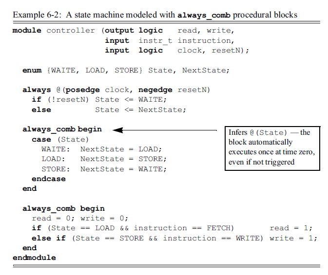
Example 6-2, below, makes one simple change to this example. The always @(State) is replaced with always_comb. The always_comb procedural block will infer a sensitivity list for all external variables that are read by the block, which in this example is State. Therefore, the always_comb infers the same sensitivity list as in example 6-1:
Even though the sensitivity lists are the same, there is an important difference between always_comb and using always @(State). An always_comb procedural block automatically executes one time at simulation time zero, after all procedural blocks have been activated. In this example, this means that at simulation time zero, NextState will be updated to reflect the value of State at time zero. When the first positive edge of clock occurs, State will transition to the value of NextState, which is a different value. This will trigger the always_comb procedure, which will then update NextState to reflect the new value of State. Using always_comb, the simulation lock problem illustrated in example 6-1 will not occur.
Example 6-2: A state machine modeled with always_comb procedural blocks
always_comb versus always @*
The Verilog-2001 standard added the ability to specify a wildcard for the @ event control, using either @* or @(*). The primary intent of the wildcard is to allow modeling combinational logic sensitivity lists without having to specify all the signals within the list.
always @* // combinational logic sensitivity
	if (!mode)
		y = a + b;
	else
		y = a - b;
always @* does not have combinational logic semantics
The inferred sensitivity list of Verilog’s @* is a convenient shortcut, and can simplify modeling complex procedural blocks with combinational logic. However, the @* construct does not require that the contents of the general-purpose always procedural block adhere to synthesizable combinational logic modeling guidelines.
The specialized always_comb procedural block not only infers the combinational logic sensitivity list, but also restricts other procedural blocks from writing to the same variables so as to help ensure true combinatorial behavior. In addition, always_comb executes automatically at time zero, to ensure output values are consistent with input values, whereas the @* sensitivity list will only trigger if at least one of the inferred signals in the list changes. This difference was illustrated in examples 6-1 and 6-2, above.
@* can be used incorrectly
The @ event control can be used both at the beginning of a procedural block, as a sensitivity list, as well as to delay execution of any statements within a procedural block. Synthesis guidelines do not support combinational event controls within a procedural block. Since @* is merely the event control with a wildcard to infer the signals in its event control list, it is syntactically possible to use (or misuse) @* within a procedural block, where it cannot be synthesized.
@* sensitivity list may not be complete
Another important distinction between @* and always_comb is in the sensitivity lists inferred. The Verilog standard defines that @* will infer sensitivity to all variables read in the statement or statement group that follows the @*. When used at the very beginning of a procedural block, this effectively infers sensitivity to all signals read within that procedural block. If a procedural block calls a function, @* will only infer sensitivity to the arguments of the task/function call.
calling functions from combinational logic blocks
A common problem in large designs is that the amount of code in a combinational procedural block can become cumbersome. One solution to prevent the size of a combinational procedural block from getting too large, is to partition the logic into multiple procedural blocks. This partitioning, however, can lead to convoluted spaghetti code, where many signals propagate through several procedural blocks. Another solution is to keep the combinational logic within one procedural block, but break the logic down to smaller sub-blocks using functions. Since functions synthesize to combinational logic, this is an effective method of structuring the code within large combinational procedural blocks.
@* might infer an incomplete sensitivity list
The Verilog @* might not infer a complete sensitivity its when functions are used to structure large blocks of combinational logic. The sensitivity list inferred by always @* only looks at the signals read directly by the always procedural block. It does not infer sensitivity to the signals read from within any functions called by the procedural block. Therefore, each function call must list all signals to be read by each function as inputs to the function, and each function definition must list these signals as formal input arguments. This modeling style restriction is not a synthesis restriction; it is only necessary due to the limitation of @*. If, as the design evolves, the signals used by a function should change, then this change must be made in both the function formal argument list and from where the function is called. This additional coding and code management reduces the benefit of using functions to structure large combinational procedural blocks.
always_comb sensitivity list includes signals read by functions
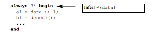
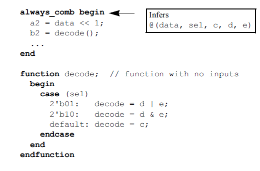
The following example illustrates the difference in sensitivity lists inferred by @* and always_comb. In this example, the procedural block using @* will only be sensitive to changes on data. The always_comb procedure will be sensitive to changes on data, sel, c, d and e.
6.2.2 Latched logic procedural blocks
always_latch represents latched logic
The always_latch procedural block is used to indicate that the intent of the procedural block is to model latched-based logic. always_latch infers its sensitivity list, just like always_comb.
always_latch
	if (enable) q <= d;
always_latch has the same semantics as always_comb
An always_latch procedural block follows the same semantic rules as with always_comb. The rules for what is to be included in the sensitivity list are the same for the two types of procedural blocks. Variables written in an always_latch procedural block cannot be written by any other procedural block. The always_latch procedural blocks also automatically execute once at time zero, in order to ensure that outputs of the latched logic are consistent with the input values at time zero.
tools can verify always_latch contents represent latched logic
What makes always_latch different than always_comb is that software tools can determine that the designer’s intent is to model latched logic, and perform different checks on the code within the procedural block than the checks that would be performed for combinational logic. For example, with latched logic, the variables representing the outputs of the procedural block do not need to be set for all possible input conditions. In the example above, a software tool could produce an error or warning if always_comb had been used, because the if statement without a matching else branch infers storage that combinational logic does not have. By specifying always_latch, software tools know that the designer’s intent is to have storage in the logic of the design. As with always_comb, these additional semantic checks on an always_latch procedural block’s contents are optional.
An example of using always_latch procedural blocks
The following example illustrates a 5-bit counter that counts from 0 to 31. An input called ready controls when the counter starts counting. The ready input is only high for a brief time. Therefore, when ready goes high, the model latches it as an internal enable signal. The latch holds the internal enable high until the counter reaches a full count of 31, and then clears the enable, preventing the counter from running again until the next time the ready input goes high.
Example 6-3: Latched input pulse using an always_latch procedural block
module register_reader (input clk, ready, resetN,
						output logic [4:0] read_pointer);

logic enable; // internal enable signal for the counter
logic overflow; // internal counter overflow flag

always_latch begin // latch the ready input
	if (!resetN)
		enable <= 0;
	else if (ready)
		enable <= 1;
	else if (overflow)
		enable <= 0;
end

always @(posedge clk, negedge resetN) begin // 5-bit counter
	if (!resetN)
		{overflow,read_pointer} <= 0;
	else if (enable)
		{overflow,read_pointer} <= read_pointer + 1;
end

endmodule
6.2.3 Sequential logic procedural blocks
always_ff represents sequential logic
The always_ff specialized procedural block indicates that the designer’s intent is to model synthesizable sequential logic behavior.
always_ff @(posedge clock, negedge resetN)
	if (!resetN) q <= 0;
	else q <= d;
A sensitivity list must be specified with an always_ff procedural block. This allows the engineer to model either synchronous or asynchronous set and/or reset logic, based on the contents of the sensitivity list.
tools can verify that always_ff contents represent sequential logic
By using always_ff to model sequential logic, software tools do not need to examine the procedural block’s contents to try to infer the type of logic intended. With the intent clearly indicated by the specialized procedural block type, software tools can instead examine the procedural block’s contents and warn if the contents cannot be synthesized as sequential logic. As with always_comb and always_latch, these additional semantic checks on an always_ff procedural block’s contents are optional.
Sequential logic sensitivity lists
always_ff enforces synthesizable sensitivity lists
The always_ff procedural block requires that every signal in the sensitivity list must be qualified with either posedge or negedge. This is a synthesis requirement for sequential logic sensitivity list. Making this rule a syntactical requirement helps ensure that simulation results will match synthesis results. An always_ff procedural block also prohibits using event controls anywhere except at the beginning of the procedural block. Event controls within the procedural block do not represent a sensitivity list for the procedural block, and are not allowed. This is also a synthesis requirement for RTL models of sequential logic.
6.2.4 Synthesis guidelines
The specialized always_comb, always_latch, and always_ff procedural blocks are synthesizable. These specialized procedural blocks are a better modeling choice than Verilog’s general purpose always procedural block whenever a model is intended to be used with both simulation and synthesis tools. The specialized procedural blocks require simulators and other software tools to check for rules that are required by synthesis compilers. The use of always_comb, always_latch, and always_ff procedural blocks can help eliminate potential modeling errors early in the design process, before models are ready to synthesize.
6.3 Enhancements to tasks and functions
SystemVerilog makes several enhancements to Verilog tasks and functions. These enhancements make it easier to model large designs in an efficient and intuitive manner.
6.3.1 Implicit task and function statement grouping
begin...end groups multiple statements
In Verilog, multiple statements within a task or function must be grouped using begin...end. Tasks also allow multiple statements to be grouped using fork...join.
SystemVerilog infers begin...end
SystemVerilog simplifies task and function definitions by not requiring the begin...end grouping for multiple statements. If the grouping is omitted, multiple statements within a task or function are executed sequentially, as if within a begin...end block.
function states_t NextState(states_t State);
	NextState = State; // default next state
	case (State)
		WAITE: if (start) NextState = LOAD;
		LOAD: if (done) NextState = STORE;
		STORE: NextState = WAITE;
	endcase
endfunction
6.3.2 Returning function values
functions create an implied variable of the same name and type
In Verilog, the function name itself is an inferred variable that is the same type as the function. The return value of a function is set by assigning a value to the name of the function. A function exits when the execution flow reaches the end of the function. The last value that was written into the inferred variable of the name of function is the value returned by the function.
function [31:0] add_and_inc (input [31:0] a,b);
	begin
		add_and_inc = a + b + 1;
	end
endfunction
SystemVerilog adds a return statement, which allows functions to return a value using return, as in C.
function int add_and_inc (input int a, b);
	return a + b + 1;
endfunction
return has priority over returning the value in the function name
To maintain backward compatibility with Verilog, the return value of a function can be specified using either the return statement or by assigning to the function name. The return statement takes precedence. If a return statement is executed, that is the value returned. If the end of the function is reached without executing a return statement, then the last value assigned to the function name is the return value, as it is in Verilog. Even when using the return statement, the name of the function is still an inferred variable, and can be used as temporary storage before executing the return statement. For example:
function int add_and_inc (input int a, b);
	add_and_inc = a + b;
	return ++add_and_inc;
endfunction
6.3.3 Returning before the end of tasks and functions
Verilog must reach the end of a task or function to exit
In Verilog, a task or function exits when the execution flow reaches the end, which is denoted by endtask or endfunction. In order to exit before the end a task or function is reached using Verilog, conditional statements such as if...else must be used to force the execution flow to jump to the end of the task or function. A task can also be forced to jump to its end using the disable keyword, but this will affect all currently running invocations of a re-entrant task. The following example requires extra coding to prevent executing the function if the input to the function is less than or equal to 1.
function automatic int log2 (input int n);
	if (n <=1)
		log2 = 1;
	else begin // skip this code when n<=1
		log2 = 0;
		while (n > 1) begin
			n = n/2;
			log2 = log2+1;
		end
	end
endfunction
the return statement can be used to exit before the end
The SystemVerilog return statement can be used to exit a task or function at any time in the execution flow, without having to reach the end of the task or function. Using return, the example above can be simplified as follows:
function automatic int log2 (input int n);
	if (n <=1) return 1; // abort function
	log2 = 0;
	while (n > 1) begin
		n = n/2;
		log2++;
	end
endfunction
Using return to exit a task or function before the end is reached can simplify the coding within the task or function, and make the execution flow more intuitive and readable.
6.3.4 Void functions
Verilog functions must return a value
In Verilog, functions must have a return value. When the function is called, the calling code must receive the return value.
void functions do not return a value
SystemVerilog adds a void type, similar to C. Functions can be explicitly declared as a void type, indicating that there is no return value from the function. Void functions are called as statements, like tasks, but have the syntax and semantic restrictions of functions. For example, functions cannot have any type of delay or event control, and cannot use nonblocking assignment statements. Another benefit of void functions is that they overcome the limitation that functions cannot call tasks, making it difficult to add coding structure to a complex function. A function can call other functions, however. Functions can call void functions, and accomplish the same structured coding style of using tasks.
Another SystemVerilog enhancement is that functions can have output and inout formal arguments. This allows a void function, which has no return value, to still propagate changes to the scope that called the function. Function formal arguments are discussed in more detail later in this chapter, in section 6.3.6 on page 157.
typedef struct {
	logic valid;
	logic [ 7:0] check;
	logic [63:0] data;
} packet_t;

function void fill_packet (
	input logic [63:0] data_in,
	output packet_t data_out );
data_out.data = data_in;
for (int i=0; i<=7; i++)
	data_out.check[i] = ^data_in[(8*i)+:8];
data_out.valid = 1;
endfunction
Synthesis guidelines
TIP: In synthesizable models, use void functions in place of tasks.
An advantage of void functions is that they can be called like a task, but must adhere to the restrictions for function contents. These restrictions, such as the requirement that functions cannot contain any event controls, help ensure proper synthesis results.
6.3.5 Passing task/function arguments by name
Verilog passes argument values by position
When a task or function is called, Verilog only allows values to be passed to the task or function in the same order in which the formal arguments of the task or function are defined. Unintentional coding errors can occur if values are passed to a task or function in the wrong order. In the following example, the order in which the arguments are passed to the divide function is important. In the call to the function, however, it is not apparent whether or not the arguments are in the correct order.
always @(posedge clock)
	result <= divide(b, a);

function int divide (input int numerator, denominator);
if (denominator == 0) begin
	$display("Error! divide by zero");
	return 0;
end
else
	return numerator / denominator;
endfunction
SystemVerilog can pass argument values by name
SystemVerilog adds the ability to pass argument values to a task or function using the names of formal arguments, rather than the order of the formal arguments. Named argument values can be passed in any order, and will be explicitly passed through the specified formal argument. The syntax for named argument passing is the same as Verilog’s syntax for named port connections to a module instance.
With SystemVerilog, the call to the function above can be coded as:
// SystemVerilog style function call
always @(posedge clock)
result <= divide(.denominator(b),
				 .numerator(a) );
named argument passing can reduce errors
Using named argument passing removes any ambiguity as to which formal argument of each value is to be passed. The code for the task or function call clearly documents the designer’s intent, and reduces the risk of inadvertent design errors that could be difficult to detect and debug.
6.3.6 Enhanced function formal arguments
Verilog functions can only have inputs
In Verilog, functions can only have inputs. The only output from a Verilog function is its single return value.
// Verilog style function formal arguments
function [63:0] add (input [63:0] a, b);
	...
endfunction
SystemVerilog functions can have inputs and outputs
SystemVerilog allows the formal arguments of functions to be declared as input, output or inout, the same a s with tasks. Allowing the function to have any number of outputs, in addition to the function return value greatly extends what can be modeled using functions.
The following code snippet shows a function that returns the result of an addition operation, plus an output formal argument that indicates if the addition operation resulted in an overflow.
// SystemVerilog style function formal args
function [63:0] add (input [63:0] a, b,
					 output overflow);
	{overflow,add} = a + b;
endfunction
Restrictions on calling functions with outputs
In order to prevent undesirable—and unsynthesizable—side effects, SystemVerilog restricts from where functions with output or inout arguments can be called. A function with output or inout arguments can not be called from:
• an event expression.
• an expression within a procedural continuous assignment.
• an expression that is not within a procedural statement.
6.3.7 Functions with no formal arguments
SystemVerilog functions can have no arguments
Verilog allows a task to have any number of formal arguments, including none. However, Verilog requires that functions have at least one input formal argument, even if the function never uses the value of that argument. SystemVerilog allows functions with no formal arguments, the same as with Verilog tasks. An example of using functions without arguments, and the benefits this style can offer, is presented in the latter part of section 6.2.1, under always_comb versus @*, on page 147.
6.3.8 Default formal argument direction and type
In Verilog, the direction of each formal argument to a task or function must be explicitly declared as an input for functions, or as input, output, or inout for tasks. A comma-separated list of arguments can follow a direction declaration. Each argument in the list will be the last direction declared.
function integer compare (input integer a,
						  input integer b);
	...
endfunction

task mytask (input a, b, output y1, y2);
	...
endtask
the default formal argument direction is input
SystemVerilog simplifies the task and function declaration syntax, by making the default direction input. Until a formal argument direction is declared, all arguments are assumed to be inputs. Once a direction is declared, subsequent arguments will be that direction, the same as in Verilog.
function int compare (int a, b);
	...
endfunction
// a and b are inputs, y1 and y2 are outputs
task mytask (a, b, output y1, y2);
	...
endtask
the default formal argument type is logic
In Verilog, each formal argument of a task or function is assumed to be a reg type, unless explicitly declared as another variable type. SystemVerilog makes the default type for task or function arguments the logic type. Since logic is synonymous with reg, this is fully compatible with Verilog.
6.3.9 Default formal argument values
each formal argument can have a default value
SystemVerilog allows an optional default value to be defined for each formal argument of a task or function. The default value is specified using a syntax similar to setting the initial value of a variable. In the following example, the formal argument count has a default value of 0, and step has a default value of 1.
function int incrementer(int count=0, step=1);
	incrementer = count + step;
endfunction
a call to a task or function can leave some arguments unspecified
When a task or function is called, it is not necessary to pass a value to the arguments that have default argument values. If nothing is passed into the task or function for that argument position, the default value is used for that call of the task or function. In the call to the incrementer function below, only one value is passed into the function, which will be passed into the first formal argument of the function. The second formal argument, step, will use its default value of 1.
always @(posedge clock)
	result = incrementer( data_bus );
TIP: Default formal argument values allow task or function calls to only pass values to the arguments unique to that call.
Specifying default argument values allows a task or function to be defined that can be used in multiple ways. In the preceding example, if the function to increment a value is called with just one argument, its default is to increment the value passed in by one. However, the function can also be passed a second value when it is called, where the second value specifies the increment amount.
SystemVerilog also changes the semantics for calling tasks or functions. Verilog requires that a task or function call have the exact same number of argument expressions as the number of task/function formal arguments. SystemVerilog allows the task or function call to have fewer argument expressions than the number of formal arguments, as in the preceding example, so long as the formal arguments that are not passed a value have a default value.
If a task or function call does not pass a value to an argument of the task or function, then the formal definition of the argument must have a default value. An error will result if a formal argument without a default value is not passed in a value.
6.3.10 Arrays, structures and unions as formal arguments
formal arguments can be structures, unions or arrays
SystemVerilog allows unpacked arrays, packed or unpacked structures and packed, unpacked, or tagged unions to be passed in or out of tasks and functions. For structures or unions, the formal argument must be defined as a structure or union type (where typedef is used to define the type). Packed arrays are treated as a vector when passed to a task or function. If the size of a packed array argument of the call does not match the size of the formal argument, the vector is truncated or expanded, following Verilog vector assignment rules. For unpacked arrays, the task or function call array argument that is passed to the task or function must exactly match the layout and element types of the definition of the array formal argument. To match, the call argument and formal argument must have the same number of array dimensions and dimension sizes, and the same packed size for each element. An example of using an unpacked array formal argument and an unpacked structure formal argument follow:
typedef struct {
	logic valid;
	logic [ 7:0] check;
	logic [63:0] data;
} packet_t;

function void fill_packet (
	input logic [7:0] data_in [0:7], // array arg
	output packet_t data_out ); // structure arg

for (int i=0; i<=7; i++) begin
	data_out.data[(8*i)+:8] = data_in[i];
	data_out.check[i] = ^data_in[i];
end
data_out.valid = 1;
endfunction
6.3.11 Passing argument values by reference instead of copy
values are passed to tasks and functions by copy
When a task or function is called, inputs are copied into the task or function. These values then become local values within the task or function. When the task or function returns at the end of its execution, all outputs are copied out to the caller of the task or function.
Verilog has implicit pass by reference task/function arguments
Verilog can reference signals that were not passed in to the task of function. For functions, this simplifies writing the function when that function is only called from one location. The function does not need to have formal arguments specified, and the call to the function does not need to list the signals to pass to the function. This style is sometimes used to break a complex procedural block into smaller, structured coding blocks. For tasks, external references to signals allows the task to sense when the external signal changes value, and for changes made within the task to immediately be sensed outside of the task, before the task has completed execution.
external name referencing uses hardcoded names
Verilog’s ability for a task or function to reference external signals is useful in both test code and RTL models. External references are synthesizable. In RTL code, external signal referencing allows values of signals to be read and/or modified without having to copy values in and out of the task or function. However, external references requires that the external signal name must be hardcoded into the task or function. This limits the ability to code a general purpose task or function that can be called several times in a module, with different signals used for each call. SystemVerilog compounds this limitiation with the addition of the ability to define tasks and function in packages, which can then be imported into any number of design blocks. Hardcoded signal names within the task or function does not work well with this mult-use methodology.
SystemVerilog has explicit pass by reference task/function arguments
SystemVerilog extends automatic tasks and functions by adding the capability to pass values by reference instead of by copy. To pass a value by reference, the formal argument is declared using the keyword ref instead of the direction keywords input, output or inout. The name of the ref argument becomes an alias for the hierarchical reference to the actual storage for the value passed to the task or function. Within the task or function, the local argument name is used instead of the external signal name. Pass by reference provides the capabilities of Verilog’s external name referencing, without having the limitations of hardcoding the external signal names into the task or function.
a ref formal arguments is an alias to the actual value
Passing by reference allows a variable to be declared in just the calling scope, and not duplicated within a task or function. Instead, the task or function refers to the variable in the scope from which it is called. Referencing a signal that was not passed into a task or function is the same as if a reference to the external signal had been implicitly passed to the task or function.
NOTE: Only automatic tasks and functions can have ref arguments
In order to have ref arguments, a task or function must be automatic. The task or function can be explicitly declared as automatic, or it can be inferred as automatic by being declared in a module, interface or program that is defined as automatic.
In the example below, a structure called data_packet and an array called raw_data are allocated in module chip. These objects are then passed as arguments in a call to the fill_packet function. Within fill_packet, the formal arguments are declared as ref arguments, instead of inputs and outputs. The formal argument data_in becomes an alias within the function for the raw_data array in the calling scope, chip. The formal argument data_out becomes an alias for the data_packet structure within chip.
module chip (...);
typedef struct {
	logic valid;
	logic [ 7:0] check;
	logic [63:0] data;
} packet_t;
packet_t data_packet;

logic [7:0] raw_data [0:7];

always @(posedge clock)
	if (data_ready)
		fill_packet (.data_in(raw_data),
					 .data_out(data_packet) );

function automatic void fill_packet (
	ref logic [7:0] data_in [0:7], // ref arg
	ref packet_t data_out ); // ref arg
for (int i=0; i<=7; i++) begin
	data_out.data[(8*i)+:8] = data_in[i];
	data_out.check[i] = ^data_in[i];
end
data_out.valid = 1;
endfunction
...
endmodule
Read-only reference arguments
pass by reference can be read-only
A reference formal argument can be declared to only allow reading of the object that is referenced, by declaring the formal argument as const ref. This can be used to allow the task or function to reference the information in the calling scope, but prohibit the task or function from modifying the information within the calling scope.
function automatic void fill_packet (
	const ref logic [7:0] data_in [0:7],
	ref packet_t data_out );
		...
endfunction
Task ref arguments are sensitive to changes
pass by reference allows sensitivity to changes
An important characteristic of ref arguments is that the logic of a task can be sensitive to when the signal in the calling scope changes value. This sensitivity to changes does not apply to function ref arguments. Since functions must execute in zero time, the function cannot contain timing controls that sense changes to arguments. In the following example, the received packet and done flag are passed by reference. This allows the wait statement to observe when the flag becomes true in the module that calls the task. If done had been copied in as an input, the wait statement would be looking at the local copy of done, which would not be updated when the done flag changed in the calling module.
typedef struct {
	logic valid;
	logic [ 7:0] check;
	logic [63:0] data;
} packet_t;

packet_t send_packet, receive_packet;

task automatic check_results (
	input packet_t sent,
	ref packet_t received,
	ref logic done );

static int error_count;
wait (done)
if (sent !== received) begin
	error_count++;
	$display("ERROR! received bad packet");
end
endtask
Ref arguments can read current values
In the preceding example, the sent packet is an input, which is copied in at the time the task is called. The received packet is passed by reference, instead of by copy. When the done flag changes, the task will compare the current value of the received packet with the copy of the sent packet from the time when the
task was called. If the received packet had been copied in, the comparison would have been made using the value of the received packet at the time the task was called, instead of at the time the done flag became true.
Ref arguments can propagate changes immediately
When task outputs are passed by copy, the value is not copied back to the calling scope until the task exits. If there are time controls or event controls between when the local copy of the task argument is changed and when the task exits, the calling scope will see the change to the variable when the task exits, and not when the local copy inside the task is assigned.
When a task output is passed by reference, the task is making its assignment directly to the variable in the calling scope. Any event controls in the calling scope that are sensitive to changes on the variable will see the change immediately, instead of waiting until the task completes its execution and output arguments are copied back to the calling scope.
Restrictions on calling functions with ref arguments
A function with ref formal arguments can modify values outside the scope of the function, and therefore has the same restrictions as functions with output arguments. A function with output, inout or ref arguments can not be called from:
• an event expression
• an expression within a continuous assignment
• an expression within a procedural continuous assignment
• an expression that is not within a procedural statement
6.3.12 Named task and function ends
SystemVerilog allows a name to be specified with the endtask or endfunction keyword. The syntax is:
endtask : <task_name>
endfunction : <function_name>
The white space before and after the colon is optional. The name specified must be the same as the name of the corresponding task or function. For example:
function int add_and_inc (int a, b);
	return a + b + 1;
endfunction : add_and_inc

task automatic check_results (
	input packet_t sent,
	ref packet_t received,
	ref logic done );
	static int error_count;
	...
endtask: check_results
Specifying a name with the endtask or endfunction keyword can help make large blocks of code easier to read, thus making the model more maintainable.
6.3.13 Empty tasks and functions
a task or function can be empty
Verilog requires that tasks and functions contain at least one statement (which can be an empty begin...end statement group). SystemVerilog allows tasks and functions to be completely empty, with no statements or statement groups at all. An empty function will return the current value of the implicit variable that represents the name of the function.
An empty task or function is a place holder for partially completed code. In a top-down design flow, creating an empty task or function can serve as documentation in a model for the place where more detailed functionality will be filled in later in the design flow.
6.4 Summary
This chapter has presented the always_comb, always_latch, and always_ff specialized procedural blocks that SystemVerilog adds to the Verilog standard. These specialized procedural blocks add semantics that increase the accuracy and portability for modeling hardware, particularly at the synthesizable RTL level of modeling. Also important is that these specialized procedural blocks make the designer’s intent clear as to what type of logic the procedural block should represent. Software tools can then examine the contents of the procedural block, and issue warnings if the code within the procedural block cannot be properly realized with the intended type of hardware.
SystemVerilog also adds a number of enhancements to Verilog tasks and functions. These enhancements include simplifications of Verilog syntax or semantic rules, as well as new capabilities for how tasks and functions can be used. Both types of changes allow modeling larger and more complex designs more quickly and with less coding.
- SystemVerilog Chapter Edition Design forsystemverilog chapter edition design systemverilog catalog edition design solutions edition chapter primer systemverilog systemverilog接口 systemverilog第一次logic 数组systemverilog systemverilog randomization dynamic array systemverilog模板vscode systemverilog xilinx vivado 2020