SystemVerilog for Design Edition 2 Chapter 9
This chapter presents the many enhancements to Verilog that SystemVerilog adds for representing and working with design hierarchy. The topics that are discussed include:
• Module prototypes
• Nested modules
• Simplified netlists of module instances
• Netlist aliasing
• Passing values through module ports
• Port connections by reference
• Enhanced port declarations
• Parameterized types and polymorphism
• Variable declarations in blocks
9.1 Module prototypes
module instances need more info to be compiled
A module instance in Verilog is a straight-forward and simple method of creating design hierarchy. For tool compilers, however, it is difficult to compile a module instance, because the definition of the module and its ports is in a different place than the module instance. To complete the compilation process of a module instance, the compiler must also at least parse the module definition in order to determine the number of ports, the size and type of the ports, and possibly the order of the ports in the module definition.
extern module declarations
SystemVerilog simplifies the compilation process by allowing users to specify a prototype of the module being instantiated. The prototype is defined using an extern keyword, followed by the declaration of a module and its ports. Either the Verilog-1995 or the Verilog-2001 style of module declarations can be used for the prototype. The Verilog-1995 module declaration style is limited to only defining the number of ports and port order of a module. The Verilog-2001 module declaration style defines the number of ports, the port order, the port vector sizes and the port types. Verilog-2001 style module declarations can also include a parameter list, which allows parameterized ports. Examples of Verilog-1995 and Verilog-2001 prototype declarations are:
// prototype using Verilog-1995 style
extern module counter (cnt, d, clock, resetN);
// prototype using Verilog-2001 style
extern module counter #(parameter N = 15)
					   (output logic [N:0] cnt,
						input wire [N:0] d,
						input wire clock,
								   load,
								   resetN);
Prototypes of a module definition also serve to document a design. Large designs can be spread across dozens of source files. When one file contains an instance of another module, some other file needs to be examined to see the definition of the instantiated module. A prototype of the module definition can be listed in the same file in which the module is instantiated.
Extern module declaration visibility
prototypes are local to the containing scope
The extern module declaration can be made in any module, at any level of the design hierarchy. The declaration is only visible within the scope in which it is defined. An external module declaration that is made outside of any module or interface boundary will be in the $unit compilation-unit declaration space. Any other module that shares the $unit space, anywhere in the design hierarchy, can instantiate the globally visible module.
In Verilog, modules can be instantiated before they are defined. The prototype for a module is an alternative to the actual definition in a compilation unit, and therefore uses a similar checking system. It is
not necessary for the extern declaration to be encountered prior to an instance of the module.
9.1.1 Prototype and actual definition
prototype and actual definition must match
SystemVerilog requires that the port list of an extern module declaration exactly match the actual module definition, including the order of the ports and the port sizes. It is a fatal error if there is any mismatch in the port lists of the two definitions.
9.1.2 Avoiding port declaration redundancy
module definition can use .* shortcut
SystemVerilog provides a convenient shortcut to reduce source code redundancy. If an extern module declaration exists for a module, it is not necessary to repeat the port declarations as part of the module definition. Instead, the actual module definition can simply place the .* characters in the port list. Software tools will automatically replace the .* with the ports defined in the extern module prototype. This saves having to define the same port list twice, once in the external module prototype, and again in the actual module definition. For example:
extern module counter #(parameter N = 15)
					   (output logic [N:0] cnt,
						input wire [N:0] d,
						input wire clock,
								   load,
								   resetN);
module counter ( .* );
	always @(posedge clock, negedge resetN) begin
		if (!resetN) cnt <= 0;
		else if (load) cnt <= d;
		else cnt <= cnt + 1;
	end
endmodule
In this example, using .* for the counter module definition infers both the parameter list and the port list from the extern declaration of the counter.
9.2 Named ending statements
9.2.1 Named module ends
A module is defined between the pair of keywords module and endmodule. With the addition of nested modules, a parent module can contain multiple endmodule declarations. This can make it difficult to read a large block of code, and determine visually which endmodule is paired with which module declaration
SystemVerilog allows a name to be specified with the endmodule keyword, using the form:
endmodule : <module_name>
The name specified with endmodule must be the same as the name of the module with which it is paired.
Specifying a name with endmodule serves to make SystemVerilog code self-documenting and easier to maintain. Several of the larger SystemVerilog code examples in this book illustrate using named module ends.
9.2.2 Named code block ends
SystemVerilog also allows an ending name to be specified with other named blocks of code. These include the keyword pairs: package...endpackage, interface...endinterface, task...endtask, function...endfunction, and begin...end, as well as other named coding blocks primarily used in testbench code.
Section 7.7 on page 192 discusses the use of ending names with begin...end pairs in more detail.
9.3 Nested (local) module declarations
module names are global
In Verilog, all module names, user-defined primitive (UDP) names, and system task and system function names (declared using the Verilog PLI) are placed in a global name space. The names of these objects can be referenced anywhere in the design hierarchy. This global access to module names provides a simple yet powerful mechanism for defining the design hierarchy. Any module can instantiate any other module, without dependencies on the order in which files are compiled.
access to module names is not restricted
However, Verilog’s global access to all elaborated module names makes it impossible to limit access to specific modules. If a complex Intellectual Property (IP) model, for example, contains its own hierarchy tree, the module names within the IP model will become globally accessible, allowing any other part of a design to directly instantiate the submodules of the IP model.
global names can cause conflicts
Verilog’s global access to all elaborated module names can also result in naming conflicts. For example, if both the user’s design and an IP model contained modules named FSM, there would be a name collision in the global name scope. If multiple IP models are used in the design, it is possible that a module name conflict will occur between two or more IP models. A name conflict will require that changes be made to either the IP model source code or the design code.
Most software tools provide proprietary solutions for name scope conflict. These solutions, however, usually require some level of user input over the compilation and/or elaboration process. Verilog- 2001 added a configuration construct to Verilog, which provide a standard solution for allowing the same module name to be used multiple times, without a conflict in the global module definition name scope. Configurations, however, are verbose, and do not address the problems of limiting where a module can be instantiated.
Nested (local) modules
modules declared within modules
SystemVerilog provides a simple and elegant solution for limiting where module names can be instantiated, and avoiding potential conflicts with other modules of the same name. The solution is to allow a module definition to be nested within another module definition. Nested modules are not visible outside of the hierarchy scope in which they are declared. For example:
module chip (input wire clock); // top level of design
	dreg i1 (clock);
	ip_core i2 (clock);
endmodule: chip

module dreg (input wire clock); // global module definition
	...
endmodule: register

module ip_core (input wire clock); // global module definition
	sub1 u1 (...);
	sub2 u2 (...);
	module sub1(...); // nested module definition
		...
	endmodule: sub1
	module sub2(...); // nested module definition
		...
	endmodule: sub2
endmodule: ip_core
The instantiated hierarchy tree for example 9-1 is:

Nested module definitions can be in separate files
a common style is to place each module in a separate file
A very common modeling style with Verilog is to place the source code for each module definition in a separate source file. Typically, the file name is the same as the module name. This style, while not a requirement of the Verilog language, is often used, because it helps to develop and maintain the source code of large designs. If several modules are contained in a single file, the source code within that file can become unwieldy and difficult to work with. Keeping each module in a separate file also facilitates the use of revision control software as part of the design process. Revision control tools allow specific users to check out specific files for modification, and can track the revision history of that file. If many modules are contained in the same file, revision control loses some of its effectiveness.
TIP: Use ‘include to avoid the convoluted code of multiple modules in the same source code file.
Nesting module definitions can lead to the source code file for the top-level module containing multiple module definitions. In addition, a nested module can become difficult to maintain, or to reuse in other designs, if the source code of the nested module is buried within the top-level module.
Using Verilog’s ‘include compiler directive with nested modules can eliminate these potential drawbacks. The definition of each nested module can be placed in a separate file, where it is easy to maintain and to reuse. The top-level module can then include the definitions of the nested module, using ‘include directives. This helps make the top-level module more compact and easier to read.
For example:
module ip_core (input logic clock);
	...
	‘include sub1.v // sub1 is a nested module
	‘include sub2.v // sub2 is a nested module
	...
endmodule

module sub1(...); // stored in file sub1.v
	...
endmodule

module sub2(...); // stored in file sub2.v
	...
endmodule
9.3.1 Nested module name visibility
nested module names are not global
The names of nested modules are not placed in the global module definition name scope with other module names. Nested module names exist in the name scope of the parent module. This means that a nested module can have the same name as a module defined elsewhere in a design, without any conflict in the global module definition name scope.
Because the name of a nested module is only visible locally in the parent module, the nested module can only be instantiated by the parent module, or the hierarchy tree below the nested module. A nested module cannot be instantiated anywhere else in a design hierarchy. In example 9-1, above, the modules chip, dreg, and ip_core are in the global name scope. These modules can be instantiated by any other module, anywhere in the design hierarchy. Modules sub1 and sub2 are nested within the definition of the ip_core module. These module names are local names within ip_core, and can only be instantiated in ip_core, or by the modules that are instantiated in ip_core.
nested module hierarchy paths
Nested modules have a hierarchical scope name, the same as with any module instance. Variables, nets, and other declarations within a nested module can be referenced hierarchically for verification purposes, just as with declarations in any other module in the design.
Nested modules can instantiate other modules
A nested module can instantiate other modules. The definitions of these modules can be in three name scopes: the global module definition name scope, the parent of the nested module, or within the nested module (as another nested module definition).
9.3.2 Instantiating nested modules
nested modules are instantiated the same as regular modules
A nested module is instantiated in the same way as a regular module. Nested modules can be explicitly instantiated any number of times within its parent. It can also be instantiated anywhere in the hierarchy tree below the parent module. The only difference between an instance of a nested module and a regular module is that the nested module can only be instantiated in the hierarchy tree at or below its parent module, whereas a regular module can be instantiated anywhere in the design hierarchy.
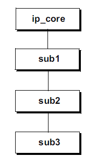
In the following example, module ip_core has three nested module definitions: sub1, sub2, and sub3. Even though the nested module definitions are local to ip_core, hierarchically, these nested modules are not all direct children of ip_core. In this example, ip_core instantiates module sub1, sub1 instantiates sub2, and sub2 instantiates sub3.
Example 9-2: Hierarchy trees with nested modules
module ip_core (input clock);
	sub1 u1 (...); // instance of nested module sub1

module sub1 (...); // nested module definition
	sub2 u2 ();
	...
endmodule: sub1

module sub2; // nested module definition
// sub2 does not have ports, but will look in its source
// code parent module (ip_core) for identifiers
	sub3 u3 (...);
endmodule: sub2

module sub3 (...); // nested module definition
	...
endmodule: sub3

endmodule: ip_core
The instantiated hierarchy tree for example 9-2 is:
9.3.3 Nested module name search rules
nested modules have a local scope
A nested module has its own name scope, just as with regular modules. Nested modules can be defined either with ports or without ports. The port names of a nested module become local names within the nested module. Any nets, variables, tasks, functions or other declarations within a nested module are local to that module.
nested modules can reference names in their parent module
Nested modules have a different name search rule than regular modules. Semantically, a nested module is similar to a Verilog task, in that the nested module has visibility to the signals within its parent. As with a task, if a name is referenced that is not in the local scope of the nested module, that name will be searched for in the parent module. If a name is referenced that is not local to the nested module and also does not exist in the parent module, the compilation-unit scope will be searched. This allows a nested module to reference variables, constants, tasks, functions, and user-defined types that are defined externally, in the compilation-unit.
modules that are not nested search upward in the instantiation tree
It is important to note that the upward searching of a nested module is different than the upward searching rules of modules that are not nested. A module that is not nested is in the global module definition scope. There is no source code parent. When a module that is defined in the global module definition scope references an identifier (such as a variable name or function name) that is not declared
within the module, the name search path uses the instantiation hierarchy tree, including the $unit compilation-unit scope.
nested modules search upward in the source code
A nested module definition, on the other hand, does have a sourcecode parent. When an identifier is referenced within a nested module that is not defined within the nested module, the search path is to look in the parent module where the nested module is defined, rather than where the module is instantiated.
9.4 Simplified netlists of module instances
netlists connect module instances together
A netlist is a list of module instances, with nets connecting the ports of the instances together. Netlists are used at many levels of design, from connecting major blocks together at a high-level of abstraction, to connecting together discrete components, such as ASIC cells or gates at a detailed implementation level. Netlists are often generated from software tools, such as synthesis compilers; but netlists are also often defined by hand, such as when connecting design blocks together. Even at the block level, with top-level models, netlists can often be quite large, with a high potential for connection errors that can be difficult to debug.
The Verilog language provides two syntax styles for connecting module instances together: ordered port connections and named port connections.
using port order to connect module instances
Ordered port connections connect a net or variable to a module instance, using the position of the ports of each module definition. For example, a net called data_bus might connect the fifth port of one module instance to the fourteenth port of another module instance. With ordered port connections, the names of each port do not matter. It is the port position that is critical. This requires knowing the exact order of the ports for each module instance being connected.
An example instance of a D-type flip-flop module is shown below.
dff d1 (out, /*not used*/, in, clock, reset);
The requirement to know the exact position of each port of the module being instantiated is a disadvantage. Unintentional design errors can easily occur when using the port order connection syntax.
Modules in complex designs often have dozens of ports. Should a net be connected to the wrong port position, the error will not be obvious from just looking at the netlist. Another disadvantage is that ordered port connections do not clearly document the design intent. It is difficult to look at a module instance that is connected by port order and determine to which port a net is intended to be connected. Because of these disadvantages, many companies discourage the use of ordered port connections in their company style guidelines.
using port names to connect module instances
The second style for connecting modules together in Verilog is to specify the name of each port explicitly, along with the name of the signal that is connected to that port. The basic syntax for each port connection is:
.<port_name>(<net_or_variable_name>)
An example instance of a D-type flip-flop module using named port connections is shown below. Since the flip-flop ports are explicitly named, it is easy to tell to what port a signal is connected, even without seeing the actual flip-flop module definition.
dff d1 (.q(out), .qb(/*not used*/),
		.d(in), .clk(clock), .rst(reset) );
Using this named port connection style, it is not necessary to maintain the order of the ports for each module instance. By using named port connections, the potential for inadvertent design errors is reduced, since each port is explicitly connected to a specific net.
Example 9-3 shows a netlist for a small microprocessor, which represents a simplified model of a MicroChip PIC 8-bit processor.
Though it is a small design with just 6 module instances in the netlist, the model illustrates using named port connections. Examples 9-4 and 9-5, which follow, show how SystemVerilog simplifies Verilog netlists.
Example 9-3: Simple netlist using Verilog’s named port connections
module miniPIC (
	inout wire [7:0] port_a_pins,
	inout wire [7:0] port_b_pins,
	inout wire [7:0] port_c_pins,
	input wire clk,
	input wire resetN
);

wire [11:0] instruct_reg, program_data;
wire [10:0] program_counter, program_address;
wire [ 7:0] tmr0_reg, status_reg, fsr_reg, w_reg, option_reg,
			reg_file_out, port_a, port_b, port_c, trisa,
			trisb, trisc, data_bus, alu_a, alu_b;
wire [ 6:0] reg_file_addr;
wire [ 3:0] alu_opcode;
wire [ 1:0] alu_a_sel, alu_b_sel;
wire 		reg_file_sel, special_reg_sel, reg_file_enable,
			w_reg_enable, zero_enable, carry_enable, skip,
			isoption, istris, polarity, carry, zero;

pc_stack pcs ( // module instance with named port connections
	.program_counter(program_counter),
	.program_address(program_address),
	.clk(clk),
	.resetN(resetN),
	.instruct_reg(instruct_reg),
	.data_bus(data_bus),
	.status_reg(status_reg)
);

prom prom (
	.dout(program_data),
	.clk(clk),
	.address(program_address)
);

instruction_decode decoder (
	.alu_opcode(alu_opcode),
	.alu_a_sel(alu_a_sel),
	.alu_b_sel(alu_b_sel),
	.w_reg_enable(w_reg_enable),
	.reg_file_sel(reg_file_sel),
	.zero_enable(zero_enable),
	.carry_enable(carry_enable),
	.polarity(polarity),
	.option(isoption),
	.tris(istris),
	.instruct_reg(instruct_reg)
);

register_files regs (
	.dout(reg_file_out),
	.tmr0_reg(tmr0_reg),
	.status_reg(status_reg),
	.fsr_reg(fsr_reg),
	.port_a(port_a),
	.port_b(port_b),
	.port_c(port_c),
	.trisa(trisa),
	.trisb(trisb),
	.trisc(trisc),
	.option_reg(option_reg),
	.w_reg(w_reg),
	.instruct_reg(instruct_reg),
	.program_data(program_data),
	.port_a_pins(port_a_pins),
	.data_bus(data_bus),
	.address(reg_file_addr),
	.clk(clk),
	.resetN(resetN),
	.skip(skip),
	.reg_file_sel(reg_file_sel),
	.zero_enable(zero_enable),
	.carry_enable(carry_enable),
	.w_reg_enable(w_reg_enable),
	.reg_file_enable(reg_file_enable),
	.zero(zero),
	.carry(carry),
	.special_reg_sel(special_reg_sel),
	.isoption(isoption),
	.istris(istris)
);

alu alu (
	.y(data_bus),
	.carry_out(carry),
	.zero_out(zero),
	.a(alu_a),
	.b(alu_b),
	.opcode(alu_opcode),
	.carry_in(status_reg[0])
);

glue_logic glue (
	.port_b_pins(port_b_pins),
	.port_c_pins(port_c_pins),
	.alu_a(alu_a),
	.alu_b(alu_b),
	.expan_out(expan_out),
	.expan_addr(expan_addr),
	.reg_file_addr(reg_file_addr),
	.reg_file_enable(reg_file_enable),
	.special_reg_sel(special_reg_sel),
	.expan_read(expan_read),
	.expan_write(expan_write),
	.skip(skip),
	.instruct_reg(instruct_reg),
	.program_counter(program_counter),
	.port_a(port_a),
	.port_b(port_b),
	.port_c(port_c),
	.data_bus(data_bus),
	.expan_in(expan_in),
	.fsr_reg(fsr_reg),
	.tmr0_reg(tmr0_reg),
	.status_reg(status_reg),
	.w_reg(w_reg),
	.reg_file_out(reg_file_out),
	.alu_a_sel(alu_a_sel),
	.alu_b_sel(alu_b_sel),
	.reg_file_sel(reg_file_sel),
	.polarity(polarity),
	.zero(zero)
);
endmodule
Named port connection advantages
named port connections are a preferred style
An advantage of named port connections is that they reduce the risk of an inadvertent design error because a net was connected to the wrong port. In addition, the named port connections better document the intent of the design. In the example above, it is very obvious which signal is intended to be connected to which port of the flip-flop, without having to go look at the source code of each module. Many companies have internal modeling guidelines that require using the named port connection style in netlists, because of these advantages.
Named port connection disadvantages
named port connections are verbose
The disadvantage of the named port connection style is that it is very verbose. Netlists can contain tens or hundreds of module instances, and each instance can have dozens of ports. Both the name of the port and the name of the net connected to the port must be listed for each and every port connection in the netlist. Port and net names can be up to 1024 characters long in Verilog tools. When long, descriptive port names and net names are used, and there are many ports for each module name, the size and verbosity of a netlist using named port connections can become excessively large and difficult to maintain.
9.4.1 Implicit .name port connections
.name is an abbreviation of named port connections
SystemVerilog provides three enhancements that greatly simplify netlists: .name (pronounced “dot-name”) port connections, .* (pronounced “dot-star”) port connections, and interfaces. The .name and .* styles are discussed in the following subsections, and interfaces are presented in Chapter 10.
.name simplifies connections to module instances
The SystemVerilog .name port connection syntax combines the advantages of both the conciseness of ordered port connections with self-documenting code and order independence of named-port connections, eliminating the disadvantages of each of the two Verilog styles. In many Verilog netlists, especially top-level netlists that connect major design blocks together, it is common to use the same name for both the port name and the name of the net connected to the port. For example, the module might have a port called data, and the interconnected net is also called data.
.name infers a connection of a net and port of the same name
Using Verilog’s named port connection style, it is necessary to repeat the name twice in order to connect the net to the port, for example: .data(data). SystemVerilog simplifies the named port connection syntax by allowing just the port name to be specified. When only the port name is given, SystemVerilog infers that a net or variable of the same name will automatically be connected to the port. This means the verbose Verilog style of .data(data) can be reduced to simply .data.
.name can be combined with named port connections
When the name of a net does not match the port to which it is to be connected, the Verilog named port connection is used to explicitly connect the net to the port. As with the Verilog named port connections,
an unconnected port can be left either unspecified, or explicitly named with an empty parentheses set to show that there is no connection.
Example 9-4 lists the simple processor model shown previously in example 9-3, but with SystemVerilog’s .name port connection style for all nets that are the same name as the port. Compare this example to example 9-3, to see how the .name syntax reduces the verbosity of named port connections. Using the .name connection style, the netlist is easier to read and to maintain.
Example 9-4: Simple netlist using SystemVerilog’s .name port connections
module miniPIC (
	inout wire [7:0] port_a_pins,
	inout wire [7:0] port_b_pins,
	inout wire [7:0] port_c_pins,
	input wire clk,
	input wire resetN
);

wire [11:0] instruct_reg, program_data;
wire [10:0] program_counter, program_address;
wire [ 7:0] tmr0_reg, status_reg, fsr_reg, w_reg, option_reg,
			reg_file_out, port_a, port_b, port_c, trisa,
			trisb, trisc, data_bus, alu_a, alu_b;
wire [ 6:0] reg_file_addr;
wire [ 3:0] alu_opcode;
wire [ 1:0] alu_a_sel, alu_b_sel;
wire 		reg_file_sel, special_reg_sel, reg_file_enable,
			w_reg_enable, zero_enable, carry_enable, skip,
			isoption, istris, polarity, carry, zero;

pc_stack pcs ( // module instance with .name port connections
	.program_counter,
	.program_address,
	.clk,
	.resetN,
	.instruct_reg,
	.data_bus,
	.status_reg
);

prom prom (
	.dout(program_data),
	.clk,
	.address(program_address)
);

instruction_decode decoder (
	.alu_opcode,
	.alu_a_sel,
	.alu_b_sel,
	.w_reg_enable,
	.reg_file_sel,
	.zero_enable,
	.carry_enable,
	.polarity,
	.option(isoption),
	.tris(istris),
	.instruct_reg
);

register_files regs (
	.dout(reg_file_out),
	.tmr0_reg,
	.status_reg,
	.fsr_reg,
	.port_a,
	.port_b,
	.port_c,
	.trisa,
	.trisb,
	.trisc,
	.option_reg,
	.w_reg,
	.instruct_reg,
	.program_data,
	.port_a_pins,
	.data_bus,
	.address(reg_file_addr),
	.clk,
	.resetN,
	.skip,
	.reg_file_sel,
	.zero_enable,
	.carry_enable,
	.w_reg_enable,
	.reg_file_enable,
	.zero,
	.carry,
	.special_reg_sel,
	.isoption,
	.istris
);

alu alu (
	.y(data_bus),
	.carry_out(carry),
	.zero_out(zero),
	.a(alu_a),
	.b(alu_b),
	.opcode(alu_opcode),
	.carry_in(status_reg[0])
);

glue_logic glue (
	.port_b_pins,
	.port_c_pins,
	.alu_a,
	.alu_b,
	.reg_file_addr,
	.reg_file_enable,
	.special_reg_sel,
	.skip,
	.instruct_reg,
	.program_counter,
	.port_a,
	.port_b,
	.port_c,
	.data_bus,
	.fsr_reg,
	.tmr0_reg,
	.status_reg,
	.w_reg,
	.reg_file_out,
	.alu_a_sel,
	.alu_b_sel,
	.reg_file_sel,
	.polarity,
	.zero
);
endmodule
.name connection inference rules
In order to infer a connection to a named port, the net or variable must match both the port name and the port vector size. In addition, the types on each side of the port must be compatible. Incompatible types are any port connections that would result in a warning or error if a net or variable is explicitly connected to the port. The rules for what connections will result in errors or warnings are defined in the IEEE 1364-2005 Verilog standard, in section 12.3.101. For example, a tri1 pullup net connected to a tri0 pulldown net through a module port will result in a warning, per the Verilog standard. Such a connection will not be inferred by the .name syntax.
These restrictions reduce the risk of unintentional connections being inferred by the .name connection style. Any mismatch in vector sizes and/or types can still be forced, using the full named port connection style, if that is the intent of the designer. Such mismatches must be explicitly specified, however. They will not be inferred from the .name syntax.
9.4.2 Implicit .* port connection
.* infers connections of all nets and ports of the same name
SystemVerilog provides an additional short cut to simplify the specification of large netlists. The .* syntax indicates that all ports and nets (or variables) of the same name should automatically be connected together for that module instance. As with the .name syntax, for a connection to be inferred, the name and vector size must match exactly, and the types connected together must be compatible. Any connections that cannot be inferred by .* must be explicitly connected together, using Verilog’s named port connection syntax.
Example 9-5 illustrates the use of SystemVerilog’s .* port connection syntax.
Example 9-5: Simple netlist using SystemVerilog’s .* port connections
module miniPIC (
	inout wire [7:0] port_a_pins,
	inout wire [7:0] port_b_pins,
	inout wire [7:0] port_c_pins,
	input wire clk,
	input wire resetN
);

wire [11:0] instruct_reg, program_data;
wire [10:0] program_counter, program_address;
wire [ 7:0] tmr0_reg, status_reg, fsr_reg, w_reg, option_reg,
			reg_file_out, port_a, port_b, port_c, trisa,
			trisb, trisc, data_bus, alu_a, alu_b;
wire [ 6:0] reg_file_addr;
wire [ 3:0] alu_opcode;
wire [ 1:0] alu_a_sel, alu_b_sel;
wire 		reg_file_sel, special_reg_sel, reg_file_enable,
			w_reg_enable, zero_enable, carry_enable, skip,
			isoption, istris, polarity, carry, zero;

pc_stack pcs ( // module instance with .* port connections
	.*
);

prom prom (
	.*,
	.dout(program_data),
	.address(program_address)
);

instruction_decode decoder (
	.*,
	.option(isoption),
	.tris(istris)
);

register_files regs (
	.*,
	.dout(reg_file_out),
	.address(reg_file_addr)
);

alu alu (
	.y(data_bus),
	.carry_out(carry),
	.zero_out(zero),
	.a(alu_a),
	.b(alu_b),
	.opcode(alu_opcode),
	.carry_in(status_reg[0])
);

glue_logic glue (
	.*
);
NOTE: SystemVerilog adds two new types of hierarchy blocks that can also have ports, interfaces (see Chapter 10), and programs (refer to the companion book, SystemVerilog for Verification). Instances of these new blocks can also use the .name and .* inferred port connections. SystemVerilog also allows calls to functions and tasks to use named connections, including the .name and .* shortcuts. This is covered in section 6.3.5 on page 156.
9.5 Net aliasing
SystemVerilog adds an alias statement that allows two different names to reference the same net. For example:
wire clock;
wire clk;
alias clk = clock;
The net clk is an alias for clock, and clock is an alias for clk. Both names refer to the same logical net.
an alias creates two or more names for the same net
Defining an alias for a net does not copy the value of one net to some other net. In the preceding example, clk is not a copy of clock. Rather, clk is clock, just referenced by a different name. Any value changes on clock will be seen by clk, since they are the same net. Conversely, any value changes on clk will be seen by clock, since they are the same net.
alias versus assign
an alias is not an assignment
The alias statement is not the same as the assign continuous assignment. An assign statement continuously copies an expression on the right-hand side of the assignment to a net or variable on the left-hand side. This is a one-way copy. The net or variable on the left-hand side reflects any changes to the expression on the right-hand side. But, if the value of the net or variable on the lefthand side is changed, the change is not reflected back to the expression on the right-hand side.
changes on any aliased net affect all aliased nets
An alias works both ways, instead of one way. Any value changes to the net name on either side of the alias statement will be reflected on the net name on the other side. This is because an alias is effectively one net with two different names.
Multiple aliases
Several nets can be aliased together. A change on any of the net names will be reflected on all of the nets that are aliased together.
wire reset, rst, resetN, rstN;
alias rst = reset;
alias reset = resetN;
alias resetN = rstN;
The previous set of aliases can also be abbreviated to a single statement containing a series of aliases, as follows:
alias rst = reset = resetN = rstN;
aliases are not order dependent
The order in which nets are listed in an alias statement does not matter. An alias is not an assignment of values, it is a list of net names that refer to the same object.
9.5.1 Alias rules
SystemVerilog imposes several restrictions on what signals can be aliased to another name.
only net types can be aliased
• Only the net types can be aliased. Variables cannot be aliased. Verilog’s net types are wire, uwire, wand, wor, tri, triand, trior, tri0, tri1, and trireg.
only nets of the same type can be aliased
• The aliased net type must be the same net type as the net to which it is aliased. A wire type can be aliased to a wire type, and a wand type can be aliased to a wand type. It is an error, however, to alias a wire to a wand or any other type.
only nets of the same size can be aliased
• The aliased net and the net to which it is aliased must be the same vector size. Note, however, that bit and part selects of nets can be aliased, so long as the vector size of the left-hand side and right-hand side of the alias statement are the same.
The following examples are all legal aliases of one net to another:
wire [31:0] n1;
wire [3:0][7:0] n2;
alias n2 = n1; // both n1 and n2 are 32 bits
wire [39:0] d_in;
wire [7:0] crc;
wire [31:0] data;
alias data = d_in[31:0]; // 32 bit nets
alias crc = d_in[39:32]; // 8 bit nets
9.5.2 Implicit net declarations
implicit nets can be inferred from an alias
An alias statement can infer net declarations. It is not necessary to first explicitly declare each of the nets in the alias. Implicit nets are inferred, following the same rules as in Verilog for inferring an implicit net when an undeclared identifier is connected to a port of a module or primitive instance. In brief, these rules are:
• An undeclared identifier name on either side of an alias statement will infer a net type.
• The default implicit net type is wire. This can be changed with the ‘default_nettype compiler directive.
• If the net name is listed as a port of the containing module, the implicit net will be the same vector size as the port.
• If the net name is not listed in the containing module’s port list, then a 1-bit net is inferred.
The following example infers single bit nets called reset and rstN, and 64 bit nets called q and d:
module register (output [63:0] q,
				 input [63:0] d,
				 input clock, reset);
wire [63:0] out, in;
alias in = d; // infers d is a 64-bit wire
alias out = q; // infers q is a 64-bit wire
alias rstN = reset; // infers 1-bit wires
...
Net aliasing can also be used to define a net that represents part of another net. In the following example, lo_byte is an alias for the lower byte of a vector, and hi_byte is an alias for the upper byte. Observe that the order of signals in the alias statement does not matter. An alias is not an assignment statement. An alias is just multiple names for the same physical wires.
module (...);
	wire [63:0] data;
	wire [7:0] lo_byte, hi_byte;
	alias data[7:0] = lo_byte;
	alias hi_byte = data[63:56];
	...
endmodule
9.5.3 Using aliases with .name and .*
The alias statement enables greater usage of the .name and .* shortcuts for modeling netlists. These shortcuts are used to connect a module port and net of the same name together, without the verbosity of Verilog’s named port connection syntax. In the following example, however, these shortcuts cannot be fully utilized to connect the clock signals together, because the port names are not the same in each of the modules.
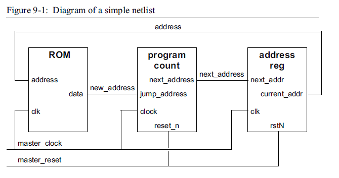
Example 9-6: Netlist using SystemVerilog’s .* port connections without aliases
module chip (input wire master_clock,
			 input wire master_reset,
			 ...);

wire [31:0] address, new_address, next_address;
ROM i1 ( .*, // infers .address(address)
		 .data(new_address),
		 .clk(master_clock) );

program_count i2 ( .*, // infers .next_address(next_address)
				   .jump_address(new_address),
				   .clock(master_clock),
				   .reset_n(master_reset) );

address_reg i3 ( .*, // no connections can be inferred
				 .next_addr(next_address),
				 .current_addr(address),
				 .clk(master_clock),
				 .rstN(master_reset) );
endmodule

module ROM (output wire [31:0] data,
			input wire [31:0] address,
			input wire clk);
	...
endmodule

module program_count (output logic [31:0] next_address,
					  input wire [31:0] jump_address,
					  input wire clock, reset_n);
	...
endmodule

module address_reg (output wire [31:0] current_addr,
					input wire [31:0] next_addr,
					input wire clk, rstN);
	...
endmodule
using aliases can simplify netlists
The master_clock in chip should be connected to all three modules in the netlist. However, the clock input ports in the modules are not called master_clock. In order for the master_clock net in the top-level chip module to be connected to the clock ports of the other modules, all of the different clock port names must be aliased to master_clock. Similar aliases can be used to connect all reset ports to the master_reset net, and to connect other ports together that do not have the same name.
Example 9-7 adds these alias statements, which allow the netlist to take full advantage of the .* shortcut to connect all modules together. In this example, wires for the vectors are explicitly declared, and wires for the different clock and reset names are implicitly declared from the alias statement.
Example 9-7: Netlist using SystemVerilog’s .* connections along with net aliases
module chip (input wire master_clock,
			 input wire master_reset,
			 ...);

wire [31:0] address, data, new_address, jump_address,
			next_address, next_addr, current_addr;

alias clk = clock = master_clock;
alias rstN = reset_n = master_reset;
alias data = new_address = jump_address;
alias next_address = next_addr;
alias current_addr = address;

ROM i1 ( .* );
program_count i2 ( .* );
address_reg i3 ( .* );

endmodule

module ROM (output wire [31:0] data,
			input wire [31:0] address,
			input wire clk);
	...
endmodule

module program_count (output logic [31:0] next_address,
					  input wire [31:0] new_count,
					  input wire clock, reset_n);
	...
endmodule

module address_reg (output wire [31:0] address,
					input wire [31:0] next_address,
					input wire clk, rstN);
	...
endmodule
In this example, the .* shortcuts infer the following connections to the module ports of the module instances:
ROM i1 (.data(data),
		.address(address)
		.clk(clk) );

program_count i2 (.next_address(next_address),
				  .jump_address(jump_address),
				  .clock(clock),
				  .reset_n(reset_n) );

address_reg i3 (.current_addr(current_addr),
				.next_addr(next_addr),
				.clk(clk),
				.rstN(rstN) );
Even though different net names are connected to different module instances, such as clk to the ROM module and clock to the program_count module, the alias statements make them the same net, and make those nets the same as master_clock.
9.6 Passing values through module ports
Verilog restrictions on module ports
The Verilog language places a number of restrictions on what types of values can be passed through the ports of a module. These restrictions affect both the definition of the module and any instances of the module. The following bullets give a brief summary of the Verilog restrictions on module ports:
• Only net types, such as the wire type, can be used on the receiving side of the port. It is illegal to connect any type of variable, such as reg or integer , to the receiving side of a module port.
• Only net, reg, and integer types, or a literal integer value can be used on the transmitting side of the port.
• It is illegal to pass the real type through module ports without first converting it to a vector using the $realtobits system function, and then converting it back to a real number, after passing through the port, with the $bitstoreal system function.
• It is illegal to pass unpacked arrays of any number of dimensions through module ports.
9.6.1 All types can be passed through ports
SystemVerilog removes most port restrictions
SystemVerilog removes nearly all restrictions on the types of values that can be passed through module ports. With SystemVerilog:
• Values of any type can be used on both the receiving and transmitting sides of module ports, including real values.
• Packed and unpacked arrays of any number of dimensions can be passed through ports.
• SystemVerilog structures and unions can be passed through module ports.
NOTE: SystemVerilog adds two new types of hierarchy blocks that can also have ports, interfaces (see Chapter 10), and programs (refer to the companion book, SystemVerilog for Verification). These new blocks have the same port connection rules as modules.
The following example illustrates the flexibility of passing values through module ports in SystemVerilog. In this example, variables are used on both sides of some ports, a structure is passed through a port, and an array, representing a look-up table, is passed through a port.
Example 9-8: Passing structures and arrays through module ports
typedef struct packed {
	logic [ 3:0] opcode;
	logic [15:0] operand;
} instruction_t;

module decoder (output logic [23:0] microcode,
				input instruction_t instruction,
				input logic [23:0] LUT [0:(2**20)-1] );
	... // do something with Look-Up-Table and instruction
endmodule

module DSP (input logic clock, resetN,
			input logic [ 3:0] opcode,
			input logic [15:0] operand,
			output logic [23:0] data );

	logic [23:0] LUT [0:(2**20)-1]; // Look Up Table
	instruction_t instruction;
	logic [23:0] microcode;
	decoder i1 (microcode, instruction, LUT);
	... // do something with microcode output from decoder
endmodule
9.6.2 Module port restrictions in SystemVerilog
SystemVerilog does place two restrictions on the values that are passed through module ports. These restrictions are intuitive, and help ensure that the module ports accurately represent the behavior of hardware.
variables can only receive values from a single source
The first restriction is that a variable type can only have a single source that writes a value to the variable at any given moment in time. A source can be:
• a single module output or inout port
• a single primitive output or inout port
• a single continuous assignment
• any number of procedural assignments
multi source logic requires net types
The reason for this single source restriction when writing to variables is that variables simply store the last value written into them. If there were multiple sources, the variable would only reflect the value of the last source to change. Actual hardware behavior for multi-source logic is different. In hardware, multiple sources, or “drivers”, are merged together, based on the hardware technology. Some technologies merge values based on the strength of the drivers, some technologies logically-and multiple drivers together, and others logically-or multiple drivers together. This implementation detail of hardware behavior is represented with Verilog net types, such as wire, wand, and wor. Therefore, SystemVerilog requires that a net type be used when a signal has multiple drivers. An error will occur if a variable is connected to two drivers.
Any number of procedural assignments is still considered a single source for writing to the variable. This is because procedural assignments are momentary statements that store a value but do not continuously update that value. For example, in an if...else programing statement, either one branch or the other can be used to update the value of the same variable, but both branches do not write to the same variable at the same time. Even multiple procedural assignments to the same variable at the same simulation time behave as temporary writes to the variable, with the last assignment executed representing the value that is actually stored in the variable. A continuous assignment or a connection to an output or inout port, on the other hand, needs to continuously update the variable to reflect the hardware behavior of a continuous electrical source.
unpacked values must have matching layouts
The second restriction SystemVerilog places on values passed through module ports is that unpacked types must be identical in layout on both sides of a module port. SystemVerilog allows structures, unions, and arrays to be specified as either packed or unpacked (see sections 5.1.3 on page 101, 5.2.1 on page 106, and 5.3.1 on page 113, respectively). When arrays, structures or unions are unpacked, the connections must match exactly on each side of the port.
For unpacked arrays, an exact match on each side of the port is when there are the same number of dimensions in the array, each dimension is the same size, and each element of the array is the same size.
For unpacked structures and unions, an exact match on each side of the port means that each side is declared using the same typedef definition. In the following example, the structure connection to the output port of the buffer is illegal. Even though the port and the connection to it are both declared as structures, and the structures have the same declarations within, the two structures are not declared from the same user-defined type, and therefore are not an exact match. The two structures cannot be connected through a module port. In this same example, however, the structure passed through the input port is legal. Both the port and the structure connected to it are declared using the same user-defined type definition. These two structures are exactly the same.
typedef struct { // unpacked structure
	logic [23:0] short_word;
	logic [63:0] long_word;
} data_t;

module buffer (input data_t in,
			   output data_t out);
	...
endmodule

module chip (...);
	data_t din; // unpacked structure
	struct { // unpacked structure
		logic [23:0] short_word;
		logic [63:0] long_word;
	} dout;

	buffer i1 (.in(din), // legal connection
			   .out(dout) // illegal connection
			   );
	...
endmodule
Packed and unpacked arrays, structures, and unions are discussed in more detail in Chapter 5.
packed values are passed through ports as vectors
The restrictions described above on passing unpacked values through ports do not apply to packed values. Packed values are stored as contiguous bits, are analogous to a vector of bits, and are passed through module ports as vectors. If the array, structure, or union are different sizes on each side of the port, Verilog’s standard rules are followed for a mismatch in vector sizes.
9.7 Reference ports
Verilog modules can have input, output and bidirectional inout ports. These port types are used to pass a value of a net or variable from one module instance to another.
a ref port passes a hierarchical reference through a port
SystemVerilog adds a fourth port type, called a ref port. A ref port passes a hierarchical reference to a variable through a port, instead of passing the value of the variable. The name of the port becomes an alias to hierarchical reference. Any references to that port name directly reference the actual source.
A reference to a variable of any type can be passed through a ref port. This includes all built-in variable types, structures, unions, enumerated types, and other user-defined types. To pass a reference to a variable through a port, the port direction is declared as ref, instead of an input, output, or inout. The type of a ref port must be the same type as the variable connected to the port.
The following example passes a reference to an array into a module, using a ref port.
Example 9-9: Passing a reference to an array through a module ref port
typedef struct packed {
	logic [ 3:0] opcode;
	logic [15:0] operand;
} instruction_t;

module decoder (output logic [23:0] microcode,
				input instruction_t instruction,
				ref logic [23:0] LUT [0:(2**20)-1] );
	... // do something with Look-Up-Table and instruction
endmodule

module DSP (input logic clock, resetN,
			input logic [ 3:0] opcode,
			input logic [15:0] operand,
			output logic [23:0] data );

	logic [23:0] LUT [0:(2**20)-1]; // Look Up Table
	instruction_t instruction;
	logic [23:0] microcode;
	decoder i1 (microcode, instruction, LUT);
	... // do something with microcode output from decoder
endmodule
9.7.1 Reference ports as shared variables
NOTE: Passing variables through ports by reference creates shared variables, which do not behave like hardware.
Passing a reference to a variable to another module makes it possible for more than one module to write to the same variable. This effectively defines a single variable that can be shared by multiple modules. That is, procedural blocks in more than one module could potentially write values into the same variable.
A variable that is written to by more than one procedural block does not behave the same as a net with multiple sources (drivers). Net types have resolution functionality that continuously merge multiple sources into a single value. A wire net, for example, resolves multiple drivers, based on strength levels. A wand net resolves multiple drivers by performing a bit-wise AND operation. Variables do not have multiple driver resolution. Variables simply store the last value deposited. When multiple modules share the same variable
through ref ports, the value of the variable at any given time will be the last value written, which could have come from any of the modules that share the variable.
9.7.2 Synthesis guidelines
NOTE: Passing references through ports is not synthesizable.
Passing references to variables through module ports is not synthesizable. It is recommended that the use of ref ports should be reserved for abstract modeling levels where synthesis is not a consideration.
9.8 Enhanced port declarations
9.8.1 Verilog-1995 port declarations
Verilog-1995 port declaration style is verbose
Verilog-1995 required a verbose set of declarations to fully declare a module’s ports. The module statement contains a port list which defines the names of the ports and the order of the ports. Following the module statement, one or more separate statements are required to declare the direction of the ports. Following the port direction declarations, additional optional statements are required to declare the types of the internal signals represented by the ports. If the types are not specified, the Verilog-1995 syntax infers a net type, which, by default, is the wire type. This default type can be changed, using the ‘default_nettype compiler directive.
module accum (data, result, co, a, b, ci);
	inout [31:0] data;
	output [31:0] result;
	output co;
	input [31:0] a, b;
	input ci;

	wire [31:0] data;
	reg [31:0] result;
	reg co;
	tri1 ci;
	...
endmodule
9.8.2 Verilog-2001 port declarations
Verilog-2001 port declaration style is more concise
Verilog-2001 introduced ANSI-C style module port declarations, which allow the port names, port size, port direction, and type declarations to be combined in the port list.
module accum (inout wire [31:0] data,
			  output reg [31:0] result,
			  output reg co,
			  input [31:0] a, b,
			  input tri1 ci );
	...
endmodule
With the Verilog-2001 port declaration syntax, the port direction is followed by an optional type declaration, and then an optional vector size declaration. If the optional type is not specified, a default type is inferred, which is the wire type, unless changed by the ‘default_nettype compiler directive. If the optional vector size
is not specified, the port defaults to the default width of the type. Following the optional width declaration is a comma-separated list of one or more port names. Each port in the list will be of the direction, type, and size specified.
in Verilog, all ports must have a direction declared
Verilog-2001’s ANSI-C style port declarations greatly simplify the Verilog-1995 syntax for module port declarations. There are, however, three limitations to the Verilog-2001 port declaration syntax:
• All ports must have a direction explicitly declared.
• The type cannot be changed for a subsequent port without respecifying the port direction.
• The vector size of the port cannot be changed for a subsequent port without re-specifying the port direction and optional type.
In the preceding example, the optional type is specified for all but the a and b input ports. These two ports will automatically infer the default type. The optional vector size is specified for the data, result, a, and b ports; but not for the co and ci ports. The unsized ports will default to the default size of their respective types, which are both 1 bit wide. The vector sizes for result and co are different. In order to change the size declaration for co, it is necessary to re-specify the port direction and type of co. Also, in the preceding example, input ports a and b do not have a type defined, and therefore default to a wire type. In order to change the type for the ci input port, the port direction must be re-specified, even though it is the same direction as the preceding ports.
9.8.3 SystemVerilog port declarations
SystemVerilog simplifies the declaration of module ports in several ways.
first port defaults to inout
First, SystemVerilog specifies a default port direction of inout (bidirectional). Therefore, it is no longer required to specify a port direction, unless the direction is different than the default.
subsequent ports default to direction of previous port
Secondly, if the next port in the port list has a type defined, but no direction is specified, the direction defaults to the direction of the previous port in the list. This allows the type specification to be changed without re-stating the port direction.
Using SystemVerilog, the Verilog-2001 module declaration for an accumulator shown on the previous page can be simplified to:
module accum (wire [31:0] data,
			  output reg [31:0] result, reg co,
			  input [31:0] a, b, tri1 ci );
	...
endmodule
The first port in the list, data, has a type, but no explicit port direction. Therefore, this port defaults to the direction of inout. Port co also has a type, but no port direction. This port defaults to the direction of the previous port in the list, which is output. Ports a and b have a port direction declared, but no type. As with Verilog-2001 and Verilog-1995, an implicit net type will be inferred, which by default is the type wire. Finally, port ci has a type declared, but no port direction. This port will inherit the direction of the previous port in the list, which is input.
NOTE: SystemVerilog adds two new types of hierarchy blocks that can also have ports, interfaces (see Chapter 10), and programs (refer to the companion book on SystemVerilog for Verification). These new blocks have the same port declaration rules as modules.
Backward compatibility
SystemVerilog remains fully backward compatible with Verilog by adding a rule that, if the first port has no direction and no type specified, then the Verilog 1995 port list syntax is inferred, and no other port in the list can have a direction or type specified within the port list.
module accum (data, result, ...);
// Verilog-1995 style because first port has no direction and no type

module accum (data, wire [31:0] result, ...);
// ERROR: cannot mix Verilog-1995 style with Verilog-2001 or SystemVerilog style
9.9 Parameterized types
parameterized modules
Verilog provides the ability to define parameter and localparam constants, and then use those constants to calculate the vector widths of module ports or other declarations. A parameter is a constant, that can be redefined at elaboration time for each instance of a module. Modules that can be redefined using parameters are often referred to as parameterized modules.
polymorphic modules using parameterized types
SystemVerilog adds a significant extension to the concept of redefinable, parameterized modules. With SystemVerilog, the net and variable types of a module can be parameterized. Parameterized types are declared using the parameter type pair of keywords. As with other parameters, parameterized types can be redefined for each instance of a module. This capability introduces an additional level of polymorphism to Verilog models. With Verilog, parameter redefinition can be used to change vector sizes and other constant characteristics for each instance of a model. With SystemVerilog, the behavior of a module can be changed based on the net and variable types of a module instance.
Parameterized types are synthesizable, provided the default or redefined types are synthesizable types.
In the following example, the variable type used by an adder is parameterized. By default, the type is shortint. Module big_chip contains three instances of the adder. Instance i1 uses the adder’s default variable type, making it a 16-bit signed adder. Instance i2 redefines the variable type to int, making this instance a 32-bit signed adder. Instance i3 redefines the variable type to int unsigned, which makes this third instance a 32-bit unsigned adder.
module adder #(parameter type ADDERTYPE = shortint)
			  (input ADDERTYPE a, b, // redefinable type
			   output ADDERTYPE sum, // redefinable type
			   output logic carry);
	ADDERTYPE temp; // local variable with redefinable type
	... // adder functionality
endmodule

module big_chip( ... );
	shortint a, b, r1;
	int c, d, r2;
	int unsigned e, f, r3;
	wire carry1, carry2, carry3;
	// 16-bit unsigned adder
	adder i1 (a, b, r1, carry1);
	// 32-bit signed adder
	adder #(.ADDERTYPE(int)) i2 (c, d, r2, carry2);
	// 32-bit unsigned adder
	adder #(.ADDERTYPE(int unsigned)) i3 (e, f, r3, carry3);
endmodule
9.10 Summary
This chapter has presented a number of important extensions to the Verilog language that allow modeling the very large netlists that occur in multi-million gate designs. Constructs such as .name and .* port connections reduce the verbosity and redundancy in netlists. net aliasing, simplified port declarations, port connections by reference, and relaxed rules on the types of values that can be passed through ports all make representing complex design hierarchy easier to model and maintain.
The next chapter presents SystemVerilog interfaces, which is another powerful construct for simplifying large netlists.
- SystemVerilog Chapter Edition Design forsystemverilog chapter edition design systemverilog catalog edition design solutions edition chapter primer systemverilog systemverilog接口 systemverilog第一次logic 数组systemverilog systemverilog randomization dynamic array systemverilog模板vscode systemverilog xilinx vivado 2020