前言
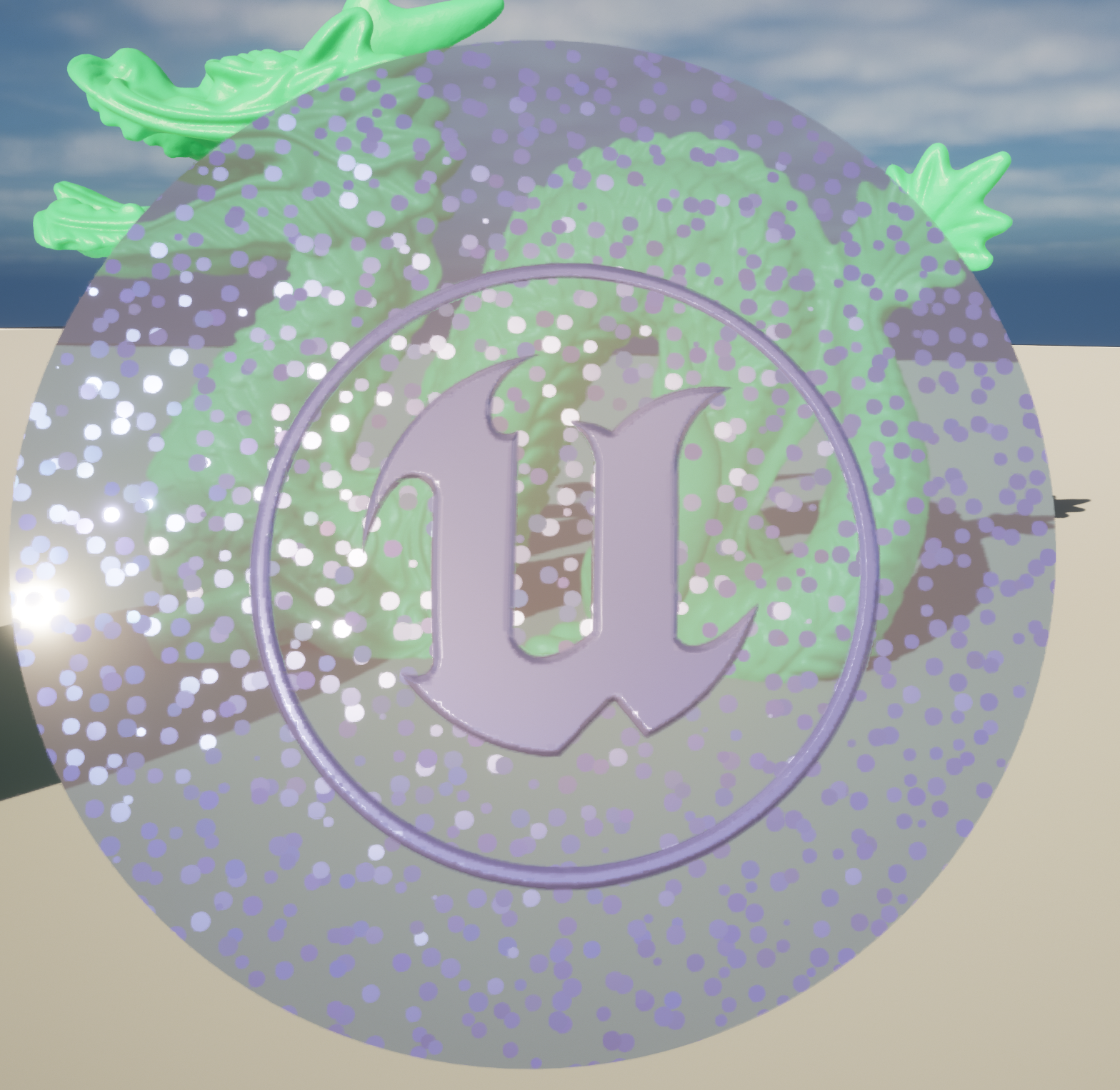
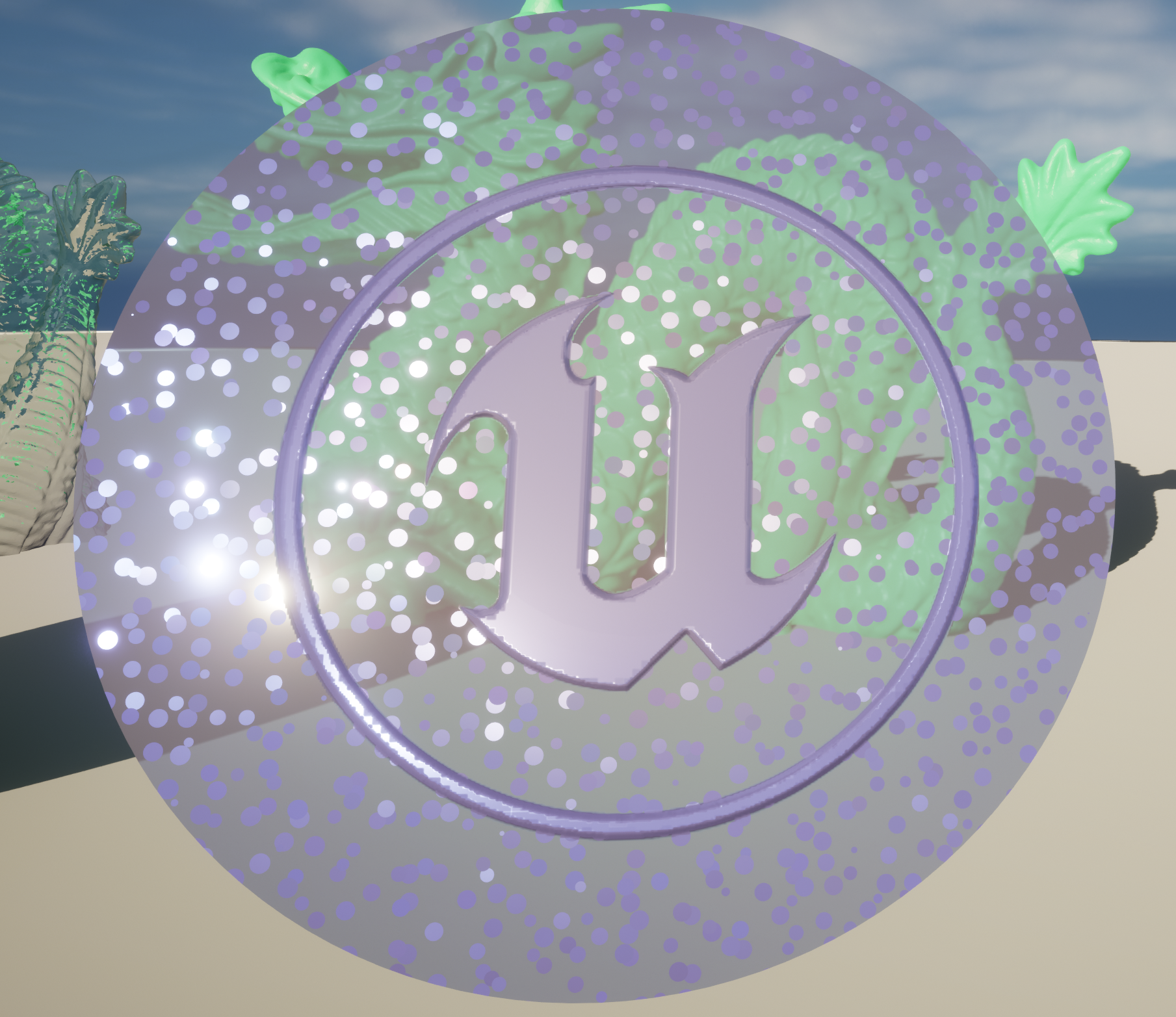
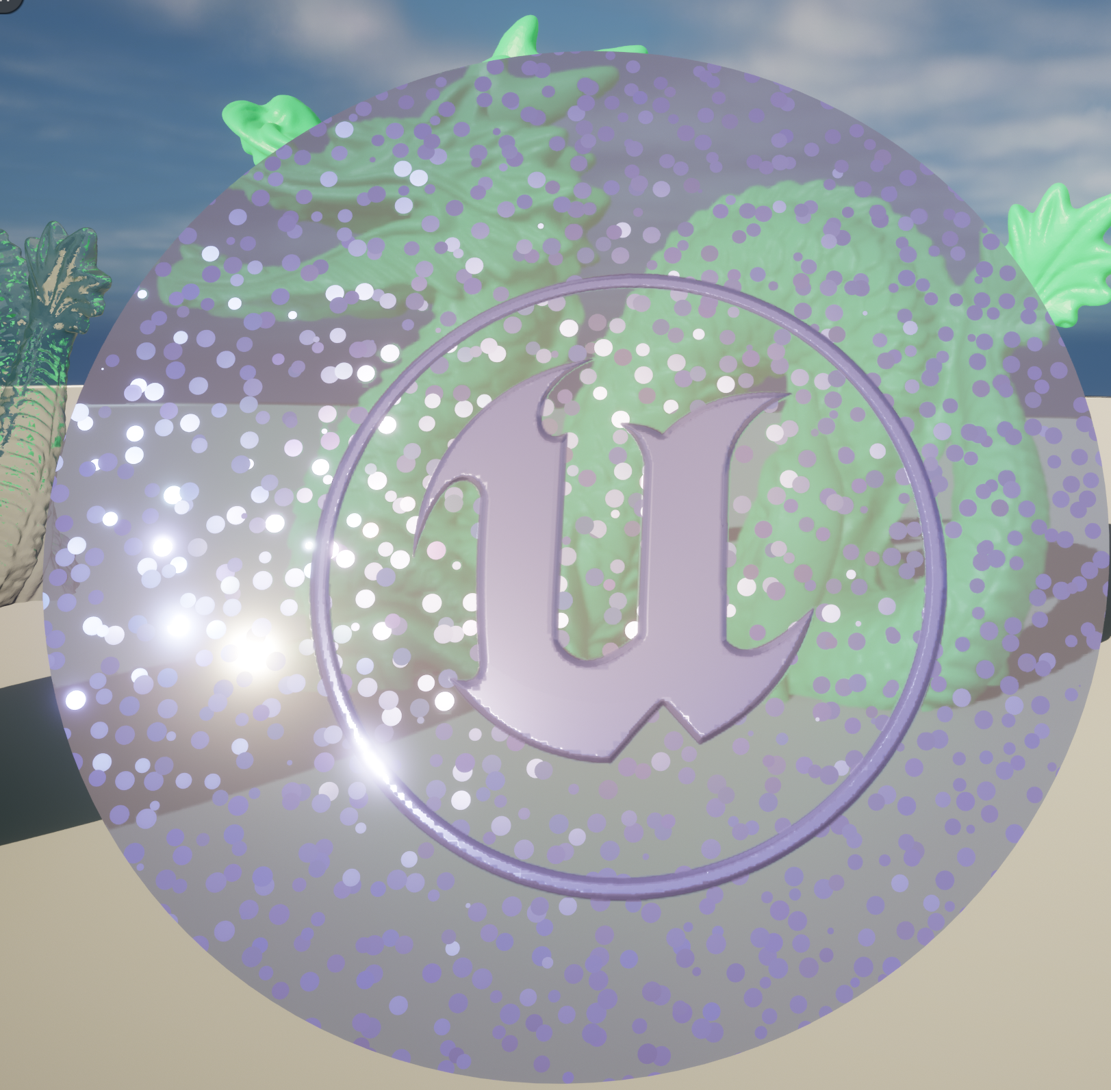
本篇将运用UE5的substrate系统制作一个亚克力圆盘
效果如下
Flake Normal Map
-
上图中圆盘内的彩色小点是通过噪声函数flake(个人翻译为薄片) normal map生成的,该函数基于[Cellular Noise]https://www.cnblogs.com/chenglixue/p/17742395.html
-
用途:汽车喷漆,及各种细小的闪光点材质
-
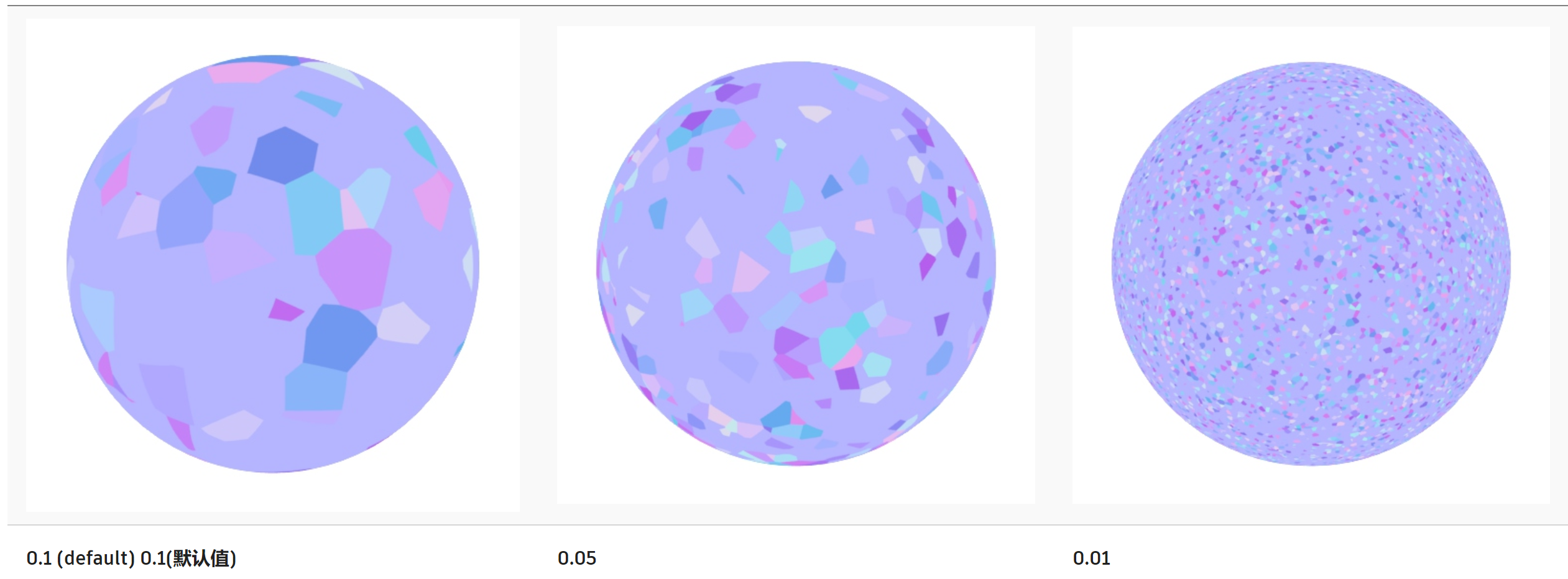
参数
- Flake Scale:缩放薄片大小
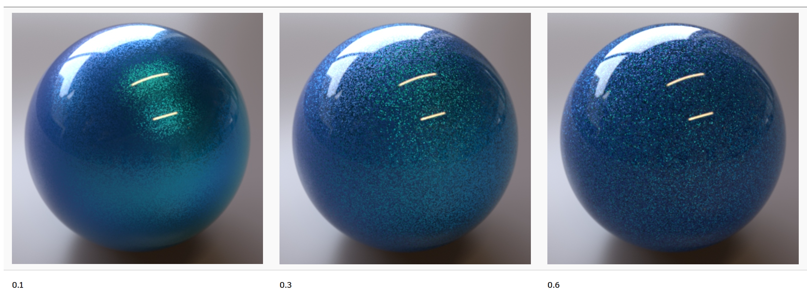
- FlakeSize:薄片尺寸大小

- Flake Size Variance:薄片尺寸的随机性——0所有薄片尺寸都相同
- Flake Normal Orientation:blend 物体表面法线 和 随机薄片的法线
- Flake Scale:缩放薄片大小
-
实现
float3 hash3(float3 p)
{
    p = float3(dot(p, float3(127.1, 311.7, 74.7)),
			  dot(p, float3(269.5, 183.3, 246.1)),
			  dot(p, float3(113.5, 271.9, 124.6)));

    return frac(sin(p) * 43758.5453123);
}

float4 flakesNormalMap(float2 fragCoord, float3 view, float flakeScale, float flakeSize, float flakeSizeVariance, float flakeNormalOrientation)
{
    float safeFlakeSizeVariance = clamp(flakeSizeVariance, 0.1, 1.0);

    // 用于求得九个特征点
    const float3 cellCenters[9] = {
		float3( 0.5,  0.5,  0.0),
		float3( 1.5,  0.5,  0.0),
		float3( 1.5,  1.5,  0.0),
		float3( 0.5,  1.5,  0.0),
		float3(-0.5,  1.5,  0.0),
		float3(-0.5,  0.5,  0.0),
		float3(-0.5, -0.5,  0.0),
		float3( 0.5, -0.5,  0.0),
		float3( 1.5, -0.5,  0.0)
	};

    // 目标像素点
    float3 position = float3(fragCoord.x, fragCoord.y, 0.f);
    position = flakeScale * position;

    float3 base = floor(position);

    float3 nearestCell = float3(0.f, 0.f, 1.f);

    int nearestCellIndex = -1;

    // 计算目标点到九个特征点的距离
    for(int cellIndex = 0; cellIndex < 9; ++cellIndex)
    {
        float3 cellCenter = base + cellCenters[cellIndex];

        float3 centerOffset = hash3(cellCenter) * 2.f - 1.f;
        centerOffset[2] *= safeFlakeSizeVariance;
        centerOffset = normalize(centerOffset);

        cellCenter += 0.5 * centerOffset;

        float cellDistance = distance(position, cellCenter);
        //是否是最小距离
        if(cellDistance < flakeSize && cellCenter[2] < nearestCell[2])
        {
            nearestCell = cellCenter;
            nearestCellIndex = cellIndex;
        }
    }

    float4 result = float4(0.f, 0.f, 1.f, 0.f);
    if(nearestCellIndex != -1)
    {
        float3 randomNormal = hash3(base + cellCenters[nearestCellIndex] + float3(0.f, 0.f, 1.5f));
        randomNormal = 2.f * randomNormal - 1.f;
        randomNormal = faceforward(randomNormal, view, randomNormal);
        randomNormal = normalize(lerp(randomNormal, float3(0.f, 0.f, 1.f), flakeNormalOrientation));

        result.xyz = float3(randomNormal.x, randomNormal.y, randomNormal.z);
        result.w = 1.f;
    }

    return result;
}
在UE中如下,”GlobalFun”custom node写有如上代码,而”Flakes Normal Map”custom node用于运行flakesNormalMap()函数
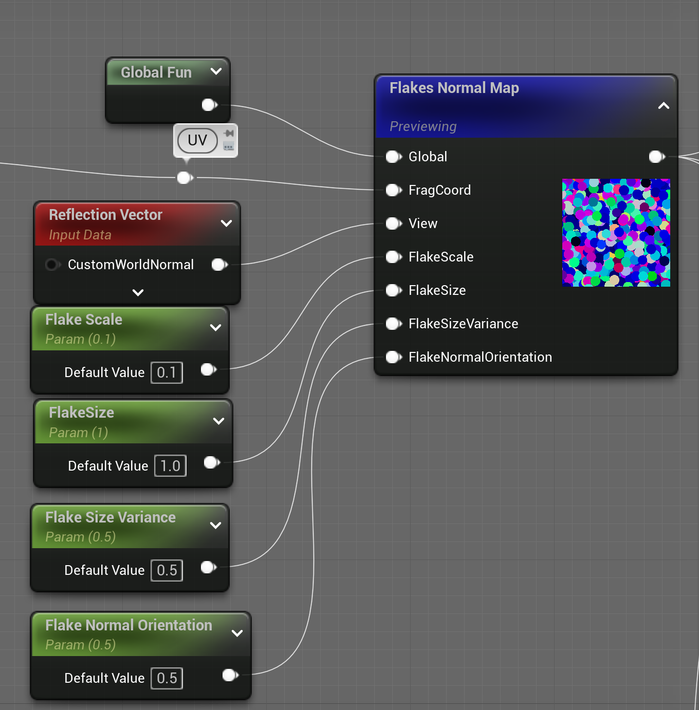
实现
前置设置
- 由于亚克力是中透明材质,因此需要将”Blend Model”设为”TranslucentColoredTransmittance”
- “Lighting Mode”设为”Surface ForwardShading”。测试了一下,改模式下材质的闪亮效果最佳,当然也是最耗性能的,而Surface TranslucencyVolume的效果非常差
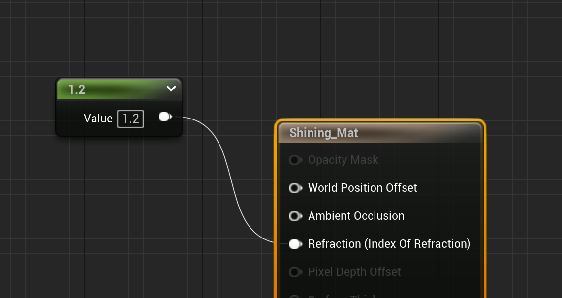
- “Refraction Method”设为”Index Of Refraction”
- 根节点处的”IOR”赋值”1.22”
确定UV
-
考虑到需要将得到的flake运用到3维物体上,需要确定uv坐标来自哪两个轴。如果这里仅仅简单地使用物体的世界坐标会得到如下的错误结果

为了根据对应的面求得正确的flake结果,需要根据vertex normal的值来确定正确的面。大致思路如下
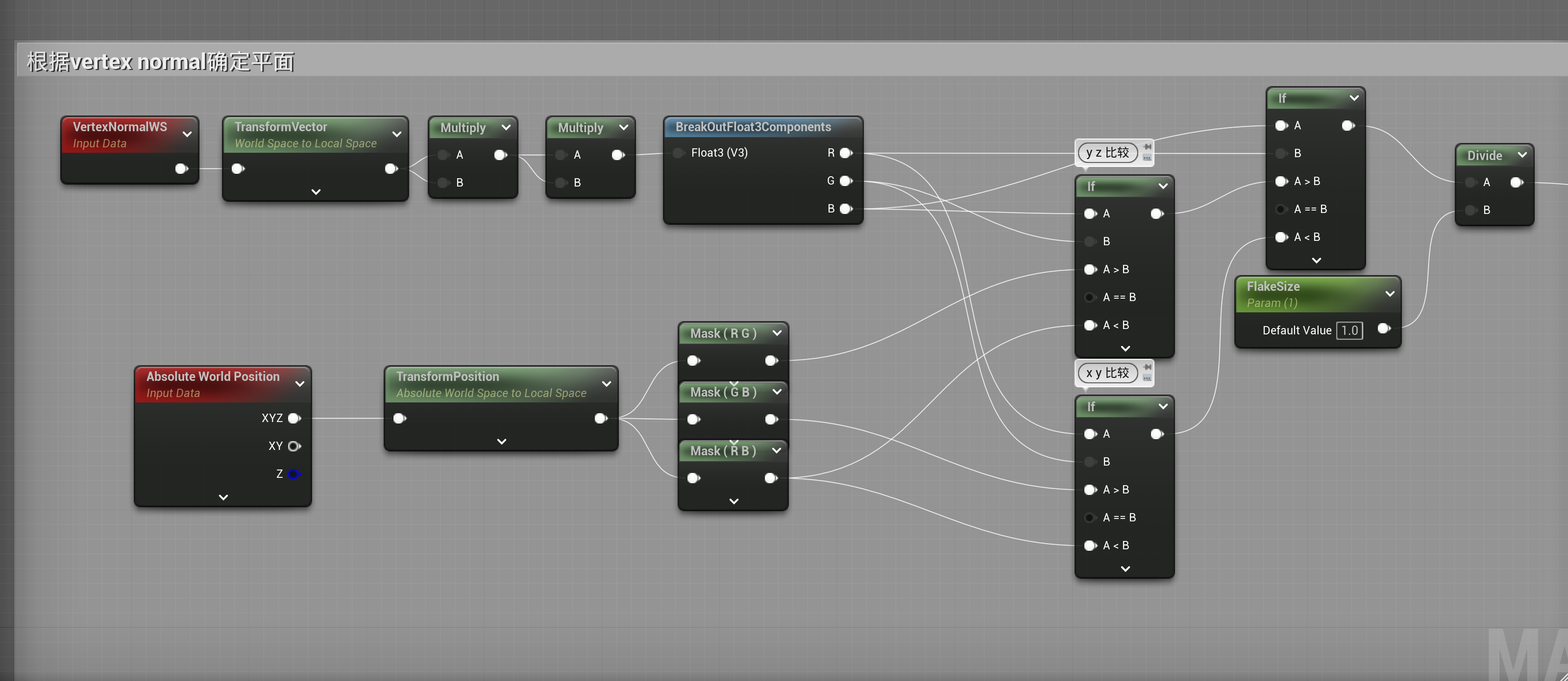
-
不难得到如下效果

制作薄片
- 目前只是求得法线信息,还需为这些薄片赋予normal、F0、F90、roughness、MFP
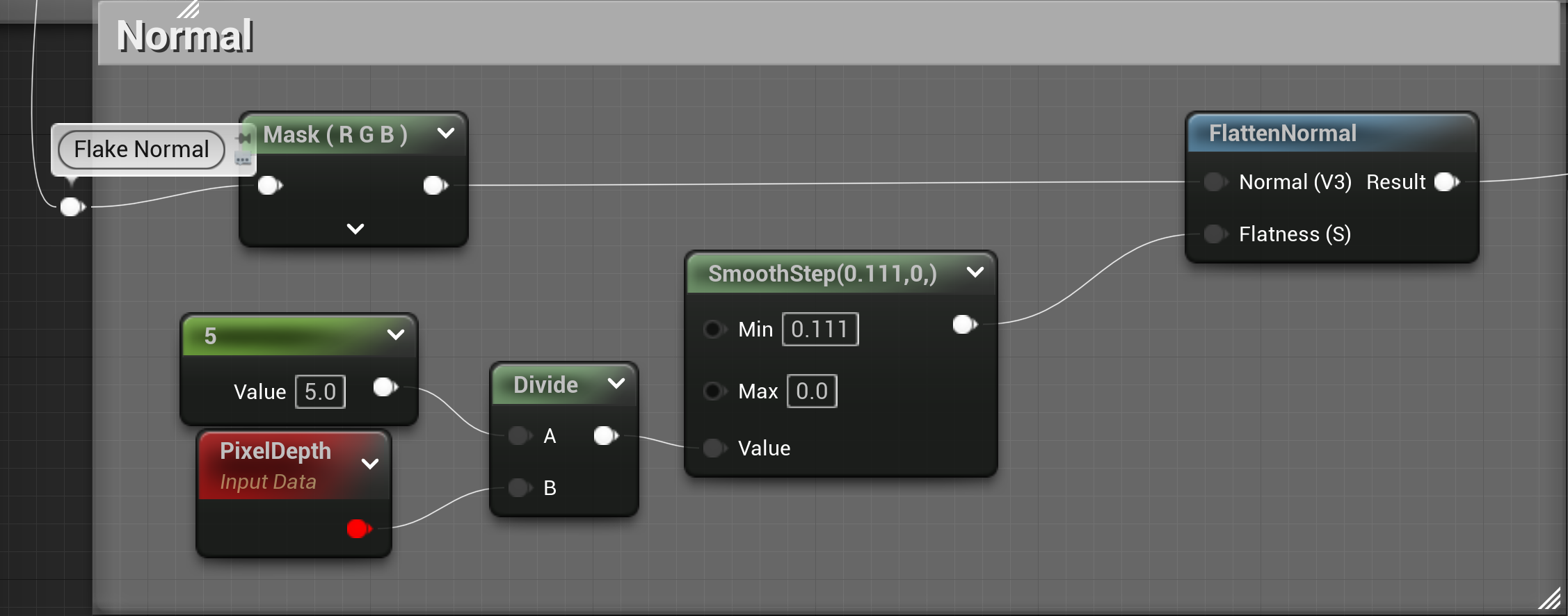
- Normal制作如下
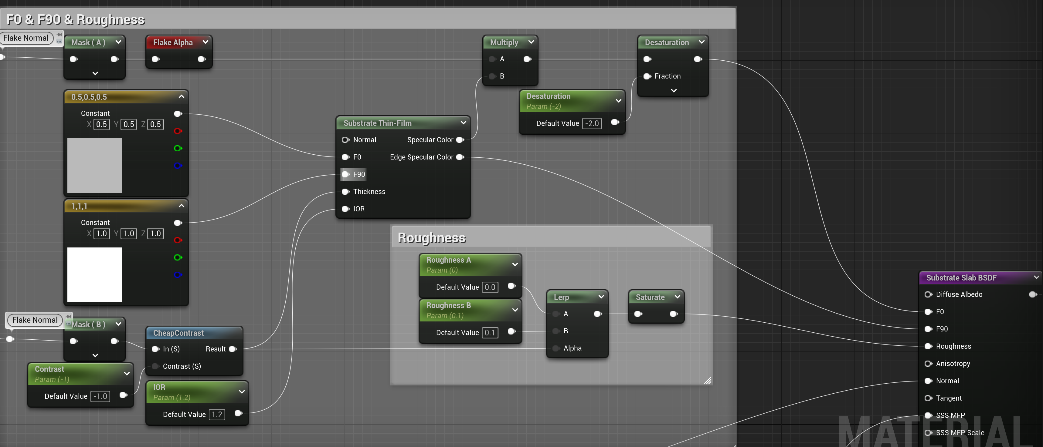
- F0 F90 Roughness制作如下
- SSS MFP
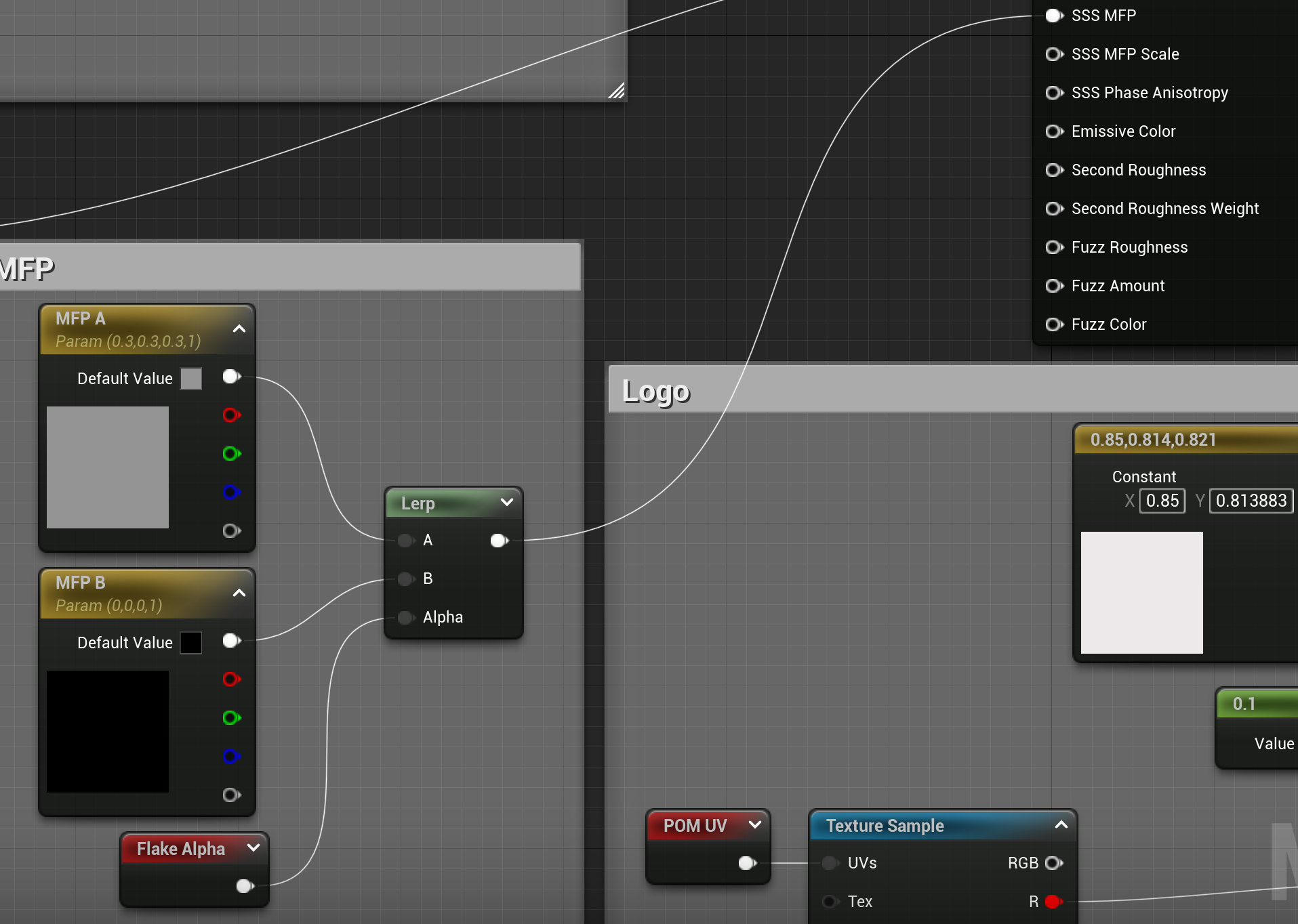
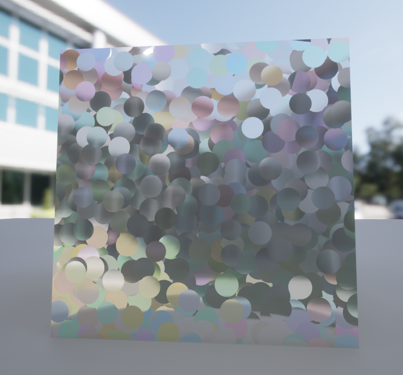
- 效果如下
刻上图案
- 为了在物体表面刻上图案,需要在水平层面上进行blend
- 实现
- 图案层
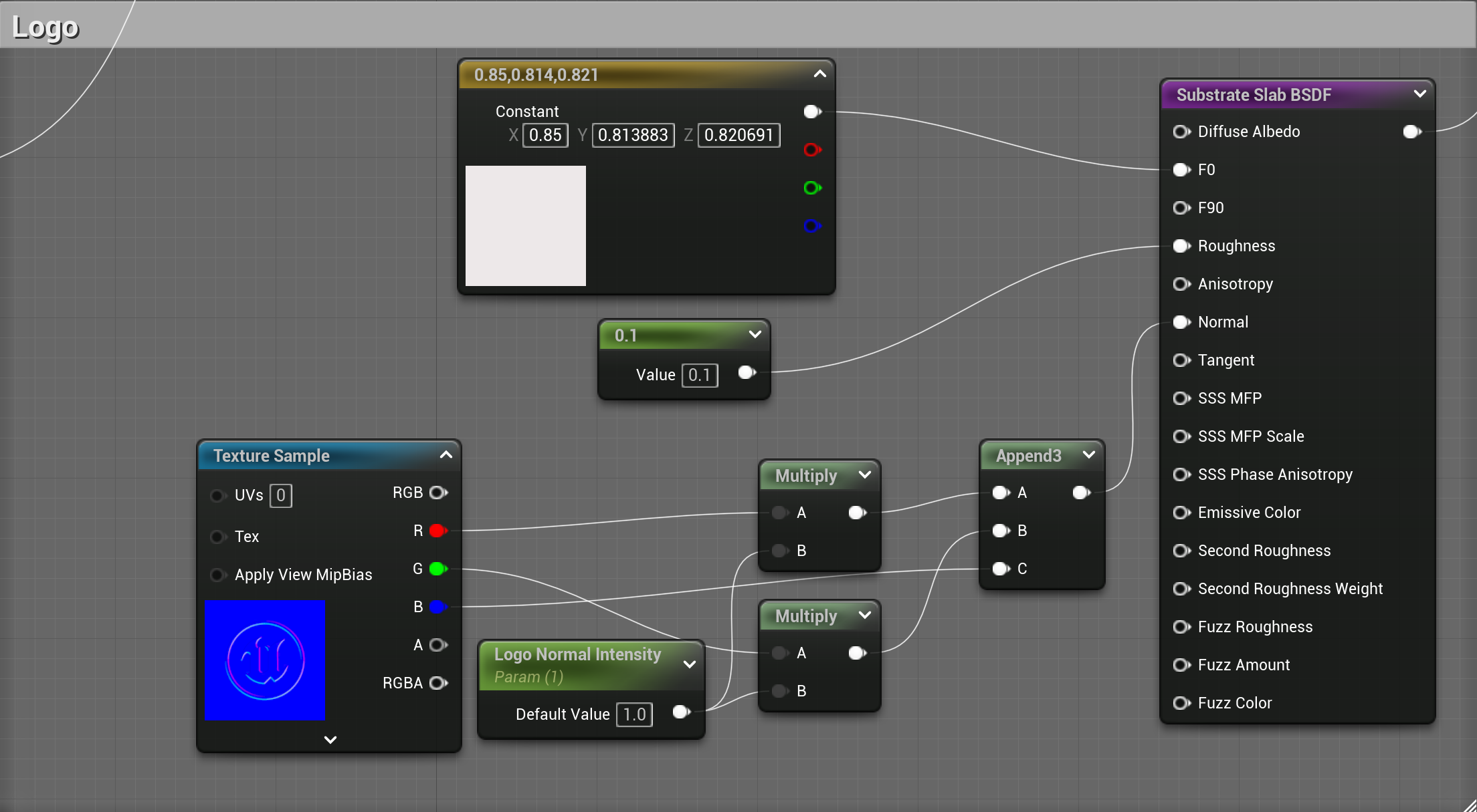
- 水平blend

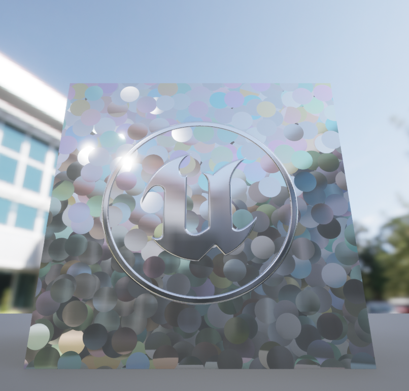
- 效果如下
- 图案层
制作亚克力
- 用了将亚克力涂于表面,需要在垂直层面进行blend
- 实现
- 亚克力
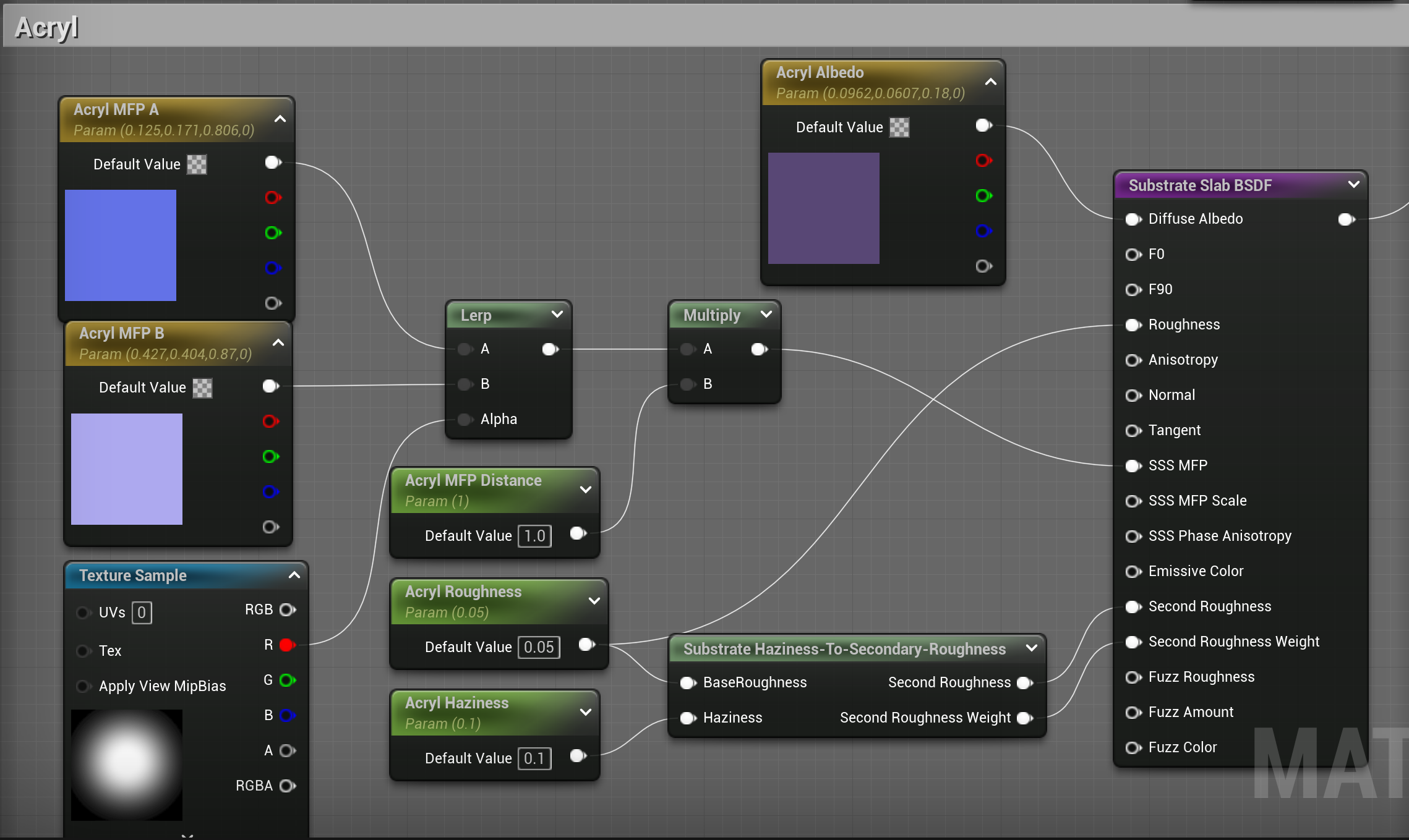
- 垂直层面的blend

- 效果

- 亚克力
折射效果
-
亚克力材质是带有较弱的折射效果的,这里使用POM实现。不使用IOR,是因为IOR只会改变材质后面物体的折射效果
-
实现
-
POM
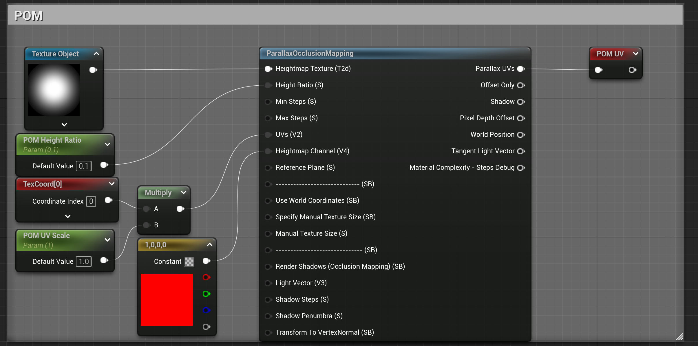
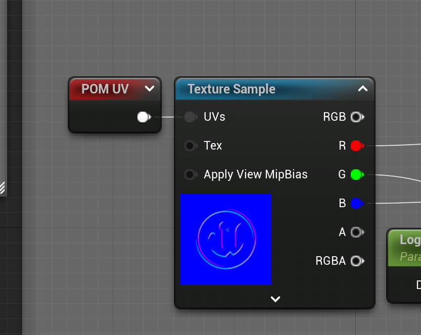
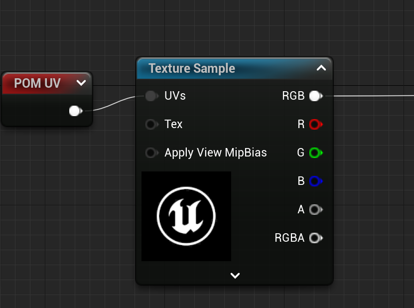
上图中的“POM UV”为”路由节点”(不懂得可以看这篇) -
在normal map 和 blend处加上POM UV
-
效果
添加POM前
添加POM后
-
后续
reference
https://docs.chaos.com/display/OSLShaders/Flakes+normal+map
https://help.autodesk.com/view/ARNOL/ENU/?guid=arnold_user_guide_ac_texture_shaders_ac_texture_flakes_html
https://zhuanlan.zhihu.com/p/658057646
UE5 内容实例