SystemVerilog for Design Edition 2 Chapter 7
SystemVerilog adds several new operators and procedural statements to the Verilog language that allow modeling more concise synthesizable RTL code. Additional enhancements convey the designer’s intent, helping to ensure that all software tools interpret the procedural statements in the same way. This chapter covers the operators and procedural statements that are synthesizable, and offers guidelines on how to properly use these new constructs.
This SystemVerilog features presented in this chapter include:
• New operators
• Enhanced for loop
• New do...while bottom testing loop
• New foreach loop
• New jump statements
• Enhanced block names
• Statement labels
• Unique and priority decisions
7.1 New operators
7.1.1 ++ and -- operators
SystemVerilog adds the ++ increment operator and the -- decrement operator to the Verilog language. These operators are used in the same way as in C. For example:
for (i = 0; i <= 31; i++ ) begin
	...
end
Post-increment and pre-increment
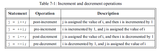
As in C, the increment and decrement operators can be used to either pre-increment/pre-decrement a variable, or to post-increment/post-decrement a variable. Table 7-1 shows the four ways in which the increment and decrement operators can be used.
The following code fragments show how pre-increment versus post increment can affect the termination value of a loop.
while (i++ < LIMIT) begin: loop1
	... // last value of i will be LIMIT
end

while (++j < LIMIT) begin: loop2
	... // last value of j will be LIMIT-1
end
In loop1, the current value of i will first be compared to LIMIT, and then i will be incremented. Therefore, the last value of i within the loop will be equal to LIMIT.
In loop2, the current value of j will first be incremented, and then the new value compared to LIMIT. Therefore, the last value of j within the loop will be one less than LIMIT.
Avoiding race conditions
The Verilog language has two assignment operators, blocking and nonblocking. The blocking assignment is represented with a single equal token ( = ), and the nonblocking assignment is represented with a less-than-equal token ( <= ).
out = in; // blocking assignment
out <= in; // nonblocking assignment
blocking and nonblocking assignments
A full explanation of blocking and nonblocking assignments is beyond the scope of this book. A number of books on the Verilog language discuss the behavior of these constructs. The primary purpose of these two assignment operators is to accurately emulate the behavior of combinational and sequential logic in zero delay models. Proper usage of these two types of assignments is critical, in order to prevent simulation event race conditions. A general guideline is to use blocking assignments to model combinational logic, and nonblocking assignments to model sequential logic.
NOTE: The ++ and -- operators behave as blocking assignments.
++ and -- behave as blocking assignments
The increment and decrement operators behave as blocking assignments. The following two statements are semantically equivalent:
i++; // increment i with blocking assign
i = i + 1; // increment i with blocking assign
++ and -- can have race conditions in sequential logic
Just as it is possible to misuse the Verilog blocking assignment, creating a race condition within simulation, it is also possible to misuse the increment and decrement operators. The following example illustrates how an increment or decrement operator could be used in a manner that would create a simulation race condition. In this example, a simple counter is incremented using the ++ operator.
The counter, which would be implemented as sequential logic using some form of flip-flops, is modeled using a sequential logic always_ff procedural block. Another sequential logic procedural block reads the current value of the counter, and performs some type of functionality based on the value of the counter.
always_ff @(posedge clock)
if (!resetN) count <= 0;
	else count++; // same as count = count + 1;

always_ff @(posedge clock)
	case (state)
		HOLD: if (count == MAX)
		...
Will count in this example be read by the second procedural block before or after count is incremented? This example has two procedural blocks that trigger at the same time, on the positive edge of clock. This creates a race condition, between the procedural block that increments count and the procedural block that reads the value of count. The defined behavior of a blocking assignment is that the software tool can execute the code above in either order. This means a concurrent process can read the value of a variable that is incremented with the ++ operator (or decremented with the -- operator) before or after the variable has changed.
The pre-increment and pre-decrement operations will not resolve this race condition between two concurrent statements. Pre- and post- increment/decrement operations affect what order a variable is read and changed within the same statement. They do not affect the order of reading and changing between concurrent statements.
A nonblocking assignment is required to resolve the race condition in the preceding example. The behavior of a nonblocking assignment is that all concurrent processes will read the value of a variable before the assignment updates the value of the variable. This properly models the behavior of a transition propagating through sequential logic, such as the counter in this example.
TIP: Avoid using ++ and -- on variables where nonblocking assignment behavior is required.
guidelines for using ++ and --
To prevent potential race conditions, the increment and decrement operators should only be used to model combinational logic. Sequential and latched logic procedural blocks should not use the increment and decrement operators to modify any variables that are to be read outside of the procedural block. Temporary variables that are only read within a sequential or latched logic procedural block can use the ++ and -- operators without race conditions. For example, a variable used to control a for loop can use the ++ or -- operators even within a sequential procedural block, so long as the variable is not read anywhere outside of the procedural block.
The proper way to model the preceding example is shown below. The ++ operator is not used, because count is representing the output of sequential logic that is to be read by another concurrent procedural block.
always_ff @(posedge clock)
	if (!resetN) count <= 0;
	else count <= count + 1; // nonblocking assign

always_ff @(posedge clock)
	case (state)
		HOLD: if (count == MAX)
			...
Synthesis guidelines
Both the pre- and post- forms of the increment and decrement operators are synthesizable. However, some synthesis compilers only support increment and decrement operations when used as a separate statement.
i++; // synthesizable
if (--i) // not synthesizable
sum = i++; // not synthesizable
7.1.2 Assignment operators
+= and other assignment operators
SystemVerilog adds several additional types of assignment operators to Verilog. These new operators combine some type of operation with the assignment.
All of the new assignment operators have the same general syntax. For example, the += operator is used as:
out += in; // add in to out, and assign result back to out
The += operator is a short cut for the statement:
out = out + in; // add and assign result to out
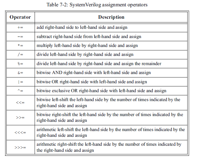
Table 7-2 lists the assignment operators which SystemVerilog adds to the Verilog language.
out = out + in; // add and assign result to out
Table 7-2 lists the assignment operators which SystemVerilog adds to the Verilog language.
NOTE: Assignment operators behave as blocking assignments
assignment operators are blocking assignments
The assignment operators have a blocking assignment behavior. To avoid simulation race conditions, the same care needs to be taken with these assignment operators as with the ++ and -- increment and decrement operators, as described in section 7.1.1 on page 170.
Synthesis guidelines
The assignment operators are synthesizable, but synthesis compilers may place restrictions on multiply and divide operations. Some synthesis compilers do not support the use of assignment operators in compound expressions.
b += 5; // synthesizable
b = (a+=5); // not synthesizable
Example 7-1 illustrates using the SystemVerilog assignment operators. The operators are used in a combinational logic procedural block, which is the correct type of procedural block for blocking assignment behavior.
Example 7-1: Using SystemVerilog assignment operators
package definitions;
	typedef enum logic [2:0] {ADD,SUB,MULT,DIV,SL,SR} opcode_t;

	typedef enum logic {UNSIGNED, SIGNED} operand_type_t;

    typedef union packed {
		logic [23:0] u_data;
		logic signed [23:0] s_data;
	} data_t;

    typedef struct packed {
		opcode_t opc;
		operand_type_t op_type;
		data_t op_a;
		data_t op_b;
	} instruction_t;
endpackage

import definitions::*; // import package into $unit space

module alu (input instruction_t instr, output data_t alu_out);
	always_comb begin
		if (instr.op_type == SIGNED) begin
			alu_out.s_data = instr.op_a.s_data;
			unique case (instr.opc)
				ADD : alu_out.s_data += instr.op_b.s_data;
				SUB : alu_out.s_data -= instr.op_b.s_data;
				MULT : alu_out.s_data *= instr.op_b.s_data;
				DIV : alu_out.s_data /= instr.op_b.s_data;
				SL : alu_out.s_data <<<= 2;
				SR : alu_out.s_data >>>= 2;
			endcase
		end
		else begin
			alu_out.u_data = instr.op_a.u_data;
			unique case (instr.opc)
				ADD : alu_out.u_data += instr.op_b.u_data;
				SUB : alu_out.u_data -= instr.op_b.u_data;
				MULT : alu_out.u_data *= instr.op_b.u_data;
				DIV : alu_out.u_data /= instr.op_b.u_data;
				SL : alu_out.u_data <<= 2;
				SR : alu_out.u_data >>= 2;
			endcase
		end
	end
endmodule
7.1.3 Equality operators with don’t care wildcards
Verilog has logical equality and case equality operators
The Verilog language has two types of equality operators, the == logical equality operator and the === case equality operator (also called the identity operator). Both operators compare two expressions, and return true if the expressions are the same, and false if they are different. A true result is represented a a one-bit logic 1 return value (1'b1), and a false result as a one-bit logic 0 return value (1'b0).
The two operators handle logic X and logic Z values in the operands differently:
• The == logical equality operator will consider any comparison where there are bits with X or Z values are in either operand to be unknown, and return a one-bit logic X (1'bx).
• The === case equality operator will perform a bit-wise comparison of the two operands, and look for an exact match of 0, 1, X and Z values in both operands. If the operands are identical, the operator will return true, otherwise, the operator will return false.
Each of these operators has a not-equal counterpart, != and !==. These operators invert the results of the true/false test, returning true if the operands are not equal, and false if they are equal. An unknown result remains unknown.
the SystemVerilog wildcard equality operator allows masking out bits
SystemVerilog adds two new comparison operators, ==? and !=?. These operators allow for don’t-care bits to be masked from the comparison. The ==? operator, referred to as the wildcard equality operator, performs a bit-wise comparison of its two operands, similar to the == logical equality operator. With the ==? wildcard equality operator, however, a logic X or a logic Z in a bit position of the right-hand operand is treated as a wildcard that will match any value in the corresponding bit position of the other operand.
Table 7-3 shows the differences in the types of equality operators.
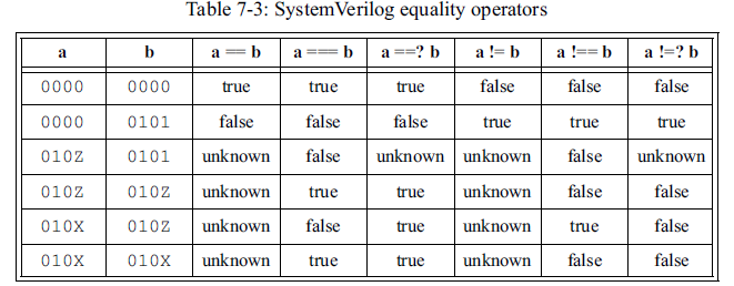
Observe that in the table above, X or Z bits in a are not masked out by a ==? b or a !=? b. These operators only consider X or Z bits in the right-hand operand as mask bits. X or Z bits in the left-hand operand are considered literal 4-state values. In Verilog, logic X in a number can be represented by the characters x or X, and logic Z in a number can be represented by the characters z, Z or ?.
logic [7:0] opcode;
...
if (opcode ==? 8’b11011???) // mask out low bits
...
If the operands are not the same size, then the wildcard equality operators will expand the vectors to the same size before performing the comparison. The vector expansion rules are the same as with the logical equality operators.
Synthesis guidelines
To synthesize the wildcard equality operator, the masked bits must be constant expressions. That is, the right-hand operand cannot be a variable where the masked bits could change during simulation.
logic [3:0] a, b;
logic y1, y2;
assign y1 = (a ==? 4’b1??1); //synthesizable
assign y2 = (a ==? b); //non synthesizable
7.1.4 Set membership operator — inside
SystemVerilog adds an operator to test if a value matches anywhere within a set of values. The operator uses the keyword, inside.
logic [2:0] a;
if ( a inside {3’b001, 3’b010, 3’b100} )
...
As with the ==? wildcard equality operator, the inside operator can simplify comparing a value to several possibilities. Without the inside operator, the preceding if decision would likely have been coded as:
if ( (a==3’b001) || (a==3’b010) || (a==3’b100} )
...
With the inside operator, the set of values to which the first value is matched can be other signals.
if ( data inside {bus1, bus2, bus3, bus4} )
...
The set of values can also be an array. The next example tests to see if the value of 13 occurs anywhere in an array called d_array.
int d_array [0:1023];
if ( 13 inside {d_array} )
...
The inside operator uses the value Z or X (Z can also be represented with ?) to represent don’t care conditions. The following test will be true if a has a value of 3’b101, 3’b111, 3’b1x1, or 3’b1z1. As with the ==? wildcard equality operator, synthesis only permits the masked bits to be specified in constant expressions.
logic [2:0] a;
if (a inside {3’b1?1})
...
The inside operator can be used with case statements, as well as with if statements.
always_comb begin
	case (instruction) inside
		4'b0???: opc = instruction[2:0];
		4'b1000, 4'b1100: opc = 3'b000;
		default: opc = 3'b111;
	endcase
end
The inside operator is similar to the casex statement, but with two important differences. First, the inside operator can be used with both if decisions and case statements. Second, the casex statement treats Z and X values on both sides of the comparison as don’t care bits. The inside operator only treats Z and X values in the set of expressions after the inside keyword (the right-hand side of the comparison) as masked, don’t care bits. Bits in the first operand, the one before the inside keyword, are not treated as don’t care bits.
Synthesis guidelines
The inside operator is synthesizable. When masked expressions are used, synthesis requires that the expressions in the value set (on the right-hand side of the inside operator) be constant expressions. At the time this book was written, some synthesis compilers were not yet supporting the inside operator
7.2 Operand enhancements
7.2.1 Operations on 2-state and 4-state types
operations with all 2-state types use Verilog operation rules
Verilog defines the rules for operations on a mix of most operand types. SystemVerilog extends these rules to also cover operations on 2-state types, which Verilog does not have. Operations on the new SystemVerilog types are performed using the same Verilog rules. This means most operations can return a value of 0, 1 or X for each bit of the result. When operations are performed on 2-state types, it is uncommon to see a result of X. Some operations on 2-state types can result in an X, however, such as a divide by 0 error.
7.2.2 Type casting
Verilog does type conversion using assignments
In Verilog, any a value of any type can be assigned to a variable of the same or any other type.Verilog automatically converts values of one type to another type using assignment statements. When a wire type is assigned to a reg variable, for example, the value on the wire (which has 4-state values, strength levels, and multi-driver resolution) is automatically converted to a reg value type (which has 4-state values, but no strength levels or multi-driver resolution). If a real type is assigned to a reg variable, the floating point value is automatically rounded off to an integer of the size of the reg bit-vector format.
The following example uses a temporary variable to convert a floating point result to a 64-bit integer value, which is then added to another integer and assigned to a 64-bit reg variable.
reg [63:0] a, y, temp;
real r;
temp = r**3; // convert result to 64-bit integer
y = a + temp;
SystemVerilog adds a type cast operator
SystemVerilog extends Verilog automatic conversion with a type cast operator. Type casting allows the designer to specify that a conversion should occur at any point during the evaluation of an expression, instead of just as part of an assignment. The syntax for type casting is:
type’(expression)
This syntax is different than C, which uses the format (type)expression. The different syntax is necessary to maintain backward compatibility with how Verilog uses parentheses, and to provide additional casting capabilities not in C (see sections 7.2.3 on page 181 on size casting and 7.2.4 on page 182 on sign casting).
Using SystemVerilog types and type casting, the Verilog example above can be coded without the use of a temporary variable, as follows:
longint a, y;
real r;
y = a + longint'(r**3);
7.2.3 Size casting
In Verilog, the number of bits of an expression is determined by the operand, the operation, and the context. The IEEE 1364-2005 Verilog standard defines the rules for determining the size of an expression. SystemVerilog follows the same rules as defined in Verilog.
vector widths can be cast to a different size
SystemVerilog extends Verilog by allowing the size of an expression to be cast to a different size. An explicit cast can be used to set the size of an operand, or to set the size of an operation result.
The syntax for the size casting operation is:
size’(expression)
Some examples of size casting are:
logic [15:0] a, b, c, sum; // 16 bits wide
logic carry; // 1 bit wide
sum = a + 16’(5); // cast operand
{carry,sum} = 17’(a + 3); // cast result
sum = a + 16’(b - 2) / c; // cast intermediate result
If an expression is cast to a smaller size than the number of bits in the expression, the left-most bits of the expression are truncated. If the expression is cast to a larger vector size, then the expression is left-extended. An unsigned expression is left-extended with 0. A signed expression is left-extended using sign extension. These are the same rules as when an expression of one size is assigned to a variable or net of a different size.
7.2.4 Sign casting
SystemVerilog follows Verilog rules for determining if an operation result is signed or unsigned. SystemVerilog also allows explicitly casting the signedness of a value. Either the signedness of an operand can be cast, or the signedness of an operation result can be cast.
The syntax for the sign casting operation is:
signed’(expression)
unsigned’(expression)
Some examples of sign casting are:
sum = signed’(a) + signed’(a); // cast operands
if (unsigned'(a-b) <= 5) // cast intermediate
... // result
The SystemVerilog sign cast operator performs the same conversion as the Verilog $signed and $unsigned system functions. Sign casting is synthesizable, following the same rules as the $signed and $unsigned system functions.
7.3 Enhanced for loops
Verilog for loop variables are declared outside the loop
In Verilog, the variable used to control a for loop must be declared prior to the loop. When multiple for loops might run in parallel (concurrent loops), separate variables must be declared for each loop. In the following example, there are three loops that can be executing at the same time.
module chip (...); // Verilog style loops
reg [7:0] i;
integer j, k;

always @(posedge clock) begin
	for (i = 0; i <= 15; i = i + 1)
		for (j = 511; j >= 0; j = j - 1) begin
		...
	end
end

always @(posedge clock) begin
	for (k = 1; k <= 1024; k = k + 2) begin
		...
	end
end
endmodule
concurrent loops can interfere with each other
Because the variable must be declared outside of the for loop, caution must be observed when concurrent procedural blocks within a module have for loops. If the same variable is inadvertently used as a loop control in two or more concurrent loops, then each loop will be modifying the control variable used by another loop. Either different variables must be declared at the module level, as in the example above, or local variables must be declared within each concurrent procedural block, as shown in the following example.
module chip (...); // Verilog style loops
...
always @(posedge clock) begin: loop1
	reg [7:0] i; // local variable
	for (i = 0; i <= 15; i = i + 1) begin
		...
	end
end

always @(posedge clock) begin: loop2
	integer i; // local variable
	for (i = 1; i <= 1024; i = i + i) begin
		...
	end
end

endmodule
7.3.1 Local variables within for loop declarations
declaring local loop variables
SystemVerilog simplifies declaring local variables for use in for loops. With SystemVerilog, the declaration of the for loop variable can be made within the for loop itself. This eliminates the need to define several variables at the module level, or to define local variables within named begin...end blocks.
In the following example, there are two loops that can be executing at the same time. Each loop uses a variable called i for the loop control. There is no conflict, however, because the i variable is local and unique for each loop.
module chip (...); // SystemVerilog style loops
...
always_ff @(posedge clock) begin
	for (bit [4:0] i = 0; i <= 15; i++)
		...
end

always_ff @(posedge clock) begin
	for (int i = 1; i <= 1024; i += 1)
		...
end
endmodule
local loop variables prevent interference
A variable declared as part of a for loop is local to the loop. References to the variable name within the loop will see the local variable, and not any other variable of the same name elsewhere in the containing module, interface, program, task, or function.
NOTE: Variables declared as part of a for loop are automatic variables.
local loop variables are automatic
When a variable is declared as part of a for loop initialization statement, the variable has automatic storage, not static storage. The variable is automatically created and initialized when the for loop is invoked, and destroyed when the loop exits. The use of automatic variables has important implications:
• Automatic variables cannot be referenced hierarchically.
• Automatic variables cannot be dumped to VCD files.
• The value of the for loop variable cannot be used outside of the for loop, because the variable does not exist outside of the loop.
local loop variables do not exist outside of the loop
The following example is illegal. The intent is to use a for loop to find the lowest bit that is set within a 64 bit vector. Because the lo_bit variable is declared as part of the for loop, however, it is only in existence while the loop is running. When the loop terminates, the variable disappears, and cannot be used after the loop.
always_comb begin
	for (int lo_bit=0; lo_bit<=63; lo_bit++) begin
		if (data[lo_bit]) break; // exit loop if
	end
    if (lo_bit > 7) // ERROR: lo_bit is not there
		...
end
When a variable needs to be referenced outside of a loop, the variable must be declared outside of the loop. The following example uses a local variable in an unnamed begin...end block (another SystemVerilog enhancement, see section 2.3 on page 26 of Chapter 2).
always_comb begin
	int lo_bit; // local variable to the block
	for (lo_bit=0; lo_bit<=63; lo_bit++) begin
		if (data[lo_bit]) break; // exit loop if
	end // bit is set
	if (lo_bit > 7) // lo_bit has last loop value
		...
end
7.3.2 Multiple for loop assignments
SystemVerilog also enhances Verilog for loops by allowing more than one initial assignment statement, and more than one step assignment statement. Multiple initial or step assignments are separated by commas. For example:
for (int i=1, j=0; i*j < 128; i++, j+=3)
...
Each loop variable can be declared as a different type.
for (int i=1, byte j=0; i*j < 128; i++, j+=3)
...
7.3.3 Hierarchically referencing variables declared in for loops
local loop variables do not have a hierarchy path
Local variables declared as part of a for loop cannot be referenced hierarchically. A testbench, waveform display, or a VCD file cannot reference the local variable (however, tools may provide proprietary, non-standard ways to access these variables).
always_ff @(posedge clock) begin
	for (int i = 0; i <= 15; i++) begin
		...// i cannot be referenced hierarchically
	end
end
When hierarchical references to a for loop control variable are required, the variable should be declared outside of the for loop, either at the module level, or in a named begin...end block.
always_ff @(posedge clock) begin : loop
	int i; // i can be referenced hierarchically
	for (i = 0; i <= 15; i++) begin
		...
	end
end
In this example, the variable i can be referenced hierarchically with the last portion of the hierarchy path ending with .loop.i .
7.3.4 Synthesis guidelines
SystemVerilog’s enhanced for loops are synthesizable, following the same synthesis coding guidelines as Verilog for loops.
7.4 Bottom testing do...while loop
Verilog has the while loop, which executes the loop as long as a loop-control test is true. The control value is tested at the beginning of each pass through the loop.
a while loop might not execute at all
It is possible that a while loop might not execute at all. This will occur if the test of the control value is false the very first time the loop is encountered in the execution flow.
This top-testing behavior of the while loop can require extra code prior to the loop, in order to ensure that any output variables of the loop are consistent with variables that would have been read by the loop. In the following example, the while loop executes as long as an input address is within the range of 128 to 255. If, however, the address is not in this range when the procedural block triggers, the while loop will not execute at all. Therefore, the range has to be checked prior to the loop, and the three loop outputs, done, OutOf-Bound, and out set for out-of-bounds address conditions, based on the value of addr.
always_comb begin
	if (addr < 128 || addr > 255) begin
		done = 0;
		OutOfBound = 1;
		out = mem[128];
	end
	else while (addr >= 128 && addr <= 255) begin
		if (addr == 128) begin
		done = 1;
		OutOfBound = 0;
	end
	else begin
		done = 0;
		OutOfBound = 0;
	end
		out = mem[addr];
		addr -= 1;
	end
end
a do...while loop will execute at least once
SystemVerilog adds a do...while loop, as in C. With the do...while loop, the control for the loop is tested at the end of each pass of the loop, instead of the beginning. This means that each time the loop is encountered in the execution flow, the loop statements will be executed at least once.
The basic syntax of a do...while loop is:
do <statement or statement block>
while (<condition>);
If the do portion of the loop contains more than one statement, the statements must be grouped using begin...end or fork...join. The while statement comes after the block of statements to be executed. Note that there is a semicolon after the while statement.
Because the statements within a do...while loop are guaranteed to execute at least once, all the logic for setting the outputs of the loop can be placed inside the loop. This bottom-testing behavior can simplify the coding of while loops, making the code more concise and more intuitive.
In the next example, the do...while loop will execute at least once, thereby ensuring that the done, OutOfBound, and out variables are consistent with the input to the loop, which is addr. No additional logic is required before the start of the loop.
always_comb begin
	do begin
		done = 0;
		OutOfBound = 0;
		out = mem[addr];
		if (addr < 128 || addr > 255) begin
			OutOfBound = 1;
			out = mem[128];
		end
		else if (addr == 128) done = 1;
		addr -= 1;
	end
	while (addr >= 128 && addr <= 255);
end
7.4.1 Synthesis guidelines
Verilog while loops are synthesizable, with a number of restrictions. These same restrictions apply to SystemVerilog’s do...while loop. The restrictions allow synthesis compilers to statically determine how many times a loop will execute. The example code snippets shown in this section represent behavioral code, and do not meet all of the RTL guidelines for synthesizing while and do...while loops.
7.5 The foreach array looping construct
SystemVerilog adds a foreach loop, which can be used to iterate over the elements of single- and multi-dimensional arrays, without having to specify the size of each array dimension. The foreach loop is discussed in section 5.4 on page 130 of Chapter 5, on arrays.
7.6 New jump statements — break, continue, return
Verilog uses the disable statement as a way to cause the execution flow of a sequence of statements to jump to a different point in the execution flow. Specifically, the disable statement causes the execution flow to jump to the end of a named statement group, or to the end of a task.
the disable statement is both a continue and a break
The Verilog disable statement can be used a variety of ways. It can be used to jump to the end of a loop, and continue execution with the next pass of the loop. The same disable statement can also be used to prematurely break out of all passes of a loop. The multiple usage of the same keyword can make it difficult to read and maintain complex blocks of code. Two ways of using disable are illustrated in the next example. The effect of the disable statement is determined by the placement of the named blocks being disabled.
// find first bit set within a range of bits
always @* begin
	begin: loop
		integer i;
		first_bit = 0;
		for (i=0; i<=63; i=i+1) begin: pass
			if (i < start_range)
				disable pass; // continue loop
			if (i > end_range)
				disable loop; // break out of loop
			if ( data[i] ) begin
				first_bit = i;
				disable loop; // break out of loop
			end
		end // end of one pass of loop
	end // end of the loop
	... // process data based on first bit set
end
the disable statement can be used as a return
The disable statement can also be used to return early from a task, before all statements in the task have been executed.
task add_up_to_max (input [ 5:0] max,
					output [63:0] result);
	integer i;
	begin
		result = 1;
		if (max == 0)
			disable add_up_to_max; // exit task
		for (i=1; i<=63; i=i+1) begin
			result = result + result;
			if (i == max)
				disable add_up_to_max; // exit task
		end
	end
endtask
The disable statement can also be used to externally disable a concurrent process or task. An external disable is not synthesizable, however.
continue, break and return statements
SystemVerilog adds the C language jump statements: break, continue and return. These jump statements can make code more intuitive and concise. SystemVerilog does not include the C goto statement.
An important difference between Verilog’s disable statement and these new jump statements is that the disable statement applies to all currently running invocations of a task or block, whereas break, continue and return only apply to the current execution flow.
7.6.1 The continue statement
The C-like continue statement jumps to the end of the loop and executes the loop control. Using the continue statement, it is not necessary to add named begin...end blocks to the code, as is required by the disable statement.
logic [15:0] array [0:255];
always_comb begin
	for (int i = 0; i <= 255; i++) begin : loop
		if (array[i] == 0)
			continue; // skip empty elements
		transform_function(array[i]);
	end // end of loop
end
7.6.2 The break statement
The C-like break statement terminates the execution of a loop immediately. The loop is not executed again unless the execution flow of the procedural block encounters the beginning of the loop again, as a new statement.
// find first bit set within a range of bits
always_comb begin
	first_bit = 0;
	for (int i=0; i<=63; i=i+1) begin
		if (i < start_range) continue;
		if (i > end_range) break; // exit loop
		if ( data[i] ) begin
			first_bit = i;
			break; // exit loop
		end
	end // end of the loop
	... // process data based on first bit set
end
The SystemVerilog break statement is used in the same way as a break in C to break out of a loop. C also uses the break statement to exit from a switch statement. SystemVerilog does not use break to exit a Verilog case statement (analogous to a C switch statement). A case statement exits automatically after a branch is executed, without needing to execute a break.
7.6.3 The return statement
SystemVerilog adds a C-like return statement, which is used to return a value from a non-void function, or to exit from a void function or a task. The return statement can be executed at any time in the execution flow of the task or function. When the return is executed, the task or function exits immediately, without needing to reach the end of the task or function.
task add_up_to_max (input [ 5:0] max,
					output [63:0] result);
	result = 1;
	if (max == 0) return; // exit task
	for (int i=1; i<=63; i=i+1) begin
		result = result + result;
		if (i == max) return; // exit task
	end
endtask
The return statement can be used to exit early from either a task or a function. The Verilog disable statement can only cause a task to exit early. It cannot be used with functions.
function automatic int log2 (input int n);
	if (n <=1) return 1; // exit function early
	log2 = 0;
	while (n > 1) begin
		n = n/2;
		log2++;
	end
	return log2;
endfunction
Note that the return keyword must not be followed by an expression in a task or void function, and must be followed by an expression in a non-void function.
7.6.4 Synthesis guidelines
The break, continue, and return jump statements are synthesizable constructs. The synthesis results are the same as if a Verilog disable statement had been used to model the same functionality.
7.7 Enhanced block names
Complex code will often have several nested begin...end statement blocks. In such code, it can be difficult to recognize which end is associated with which begin.
code can have several nested begin...end blocks
The following example illustrates how a single procedural block might contain several nested begin...end blocks. Even with proper indenting and keyword bolding as used in this short example, it can be difficult to see which end belongs with which begin.
Example 7-2: Code snippet with unnamed nested begin...end blocks
always_ff @(posedge clock, posedge reset)
	begin
		logic breakVar;
	if (reset) begin
		... // reset all outputs
	end
	else begin
		case (SquatState)
			wait_rx_valid:
				begin
					Rxready <= '1;
					breakVar = 1;
					for (int j=0; j<NumRx; j+=1) begin
						for (int i=0; i<NumRx; i+=1) begin
							if (Rxvalid[i] && RoundRobin[i] && breakVar)
								begin
									ATMcell <= RxATMcell[i];
									Rxready[i] <= 0;
									SquatState <= wait_rx_not_valid;
									breakVar = 0;
								end
						end
					end
				end
			... // process other SquatState states
		endcase
	end
end
named ends can be paired with named begins
Verilog allows a statement block to have a name, by appending :<name> after the begin keyword. The block name creates a local hierarchy scope that serves to identify all statements within the block. SystemVerilog allows (but does not require) a matching block name after the end keyword. This additional name does not affect the block semantics in any way, but does serve to enhance code readability by documenting which statement group is being completed.
To specify a name to the end of a block, a :<name> is appended after the end keyword. White space is allowed, but not required, before and after the colon.
begin: <block_name>
	...
end: <block_name>
The optional block name that follows an end must match exactly the name with the corresponding begin. It is an error for the corresponding names to be different.
The following code snippet modifies example 7-2 on the previous page by adding names to the begin...end statement groups, helping to make the code easier to read.
Example 7-3: Code snippet with named begin and named end blocks
always_ff @(posedge clock, posedge reset)
	begin: FSM_procedure
		logic breakVar;
		if (reset) begin: reset_logic
			... // reset all outputs
		end: reset_logic
		else begin: FSM_sequencer
			unique case (SquatState)
				wait_rx_valid:
					begin: rx_valid_state
						Rxready <= '1;
						breakVar = 1;
						for (int j=0; j<NumRx; j+=1) begin: loop1
							for (int i=0; i<NumRx; i+=1) begin: loop2
								if (Rxvalid[i] && RoundRobin[i] && breakVar)
									begin: match
										ATMcell <= RxATMcell[i];
										Rxready[i] <= 0;
										SquatState <= wait_rx_not_valid;
										breakVar = 0;
									end: match
							end: loop2
						end: loop1
					end: rx_valid_state
				... // process other SquatState states
			endcase
		end: FSM_sequencer
	end: FSM_procedure
7.8 Statement labels
a named block identifies a group of statements
In addition to named blocks of statements, SystemVerilog allows a label to be specified before any procedural statement. Statement labels use the same syntax as C:
<label> : <statement>
a statement label identifies a single statement
A statement label is used to identify a single statement, whereas a named statement block identifies a block of one of more statements.
always_comb begin : decode_block
	decoder : case (opcode)
		2’b00:
			outer_loop: for (int i=0; i<=15; i++)
				inner_loop: for (int j=0; j<=15; j++)
					//...
		... // decode other opcode values
	endcase
end : decode_block
a labeled statement can help document code
Statement labels document specific lines of code, which can help make the code more readable, and can make it easier to reference those lines of code in other documentation. Statement labels can also be useful to identify specific lines of code for debug utilities and code coverage analysis tools. Statement labels also allow statements to be referenced by name. A statement that is in the process of execution can be aborted using the disable statement, in the same way that a named statement group or task can be disabled.
Labeled statement blocks
a statement block can have a name or a label
A begin...end block is a statement, and can therefore have either a statement label or a block name.
begin: block1 // named block
	...
end: block1
block2: begin // labeled block
	...
end
It is illegal to give a statement block both a label and a block name.
7.9 Enhanced case statements
The Verilog case, casex, and casez statements allow the selection of one branch of logic out of multiple choices. For example:
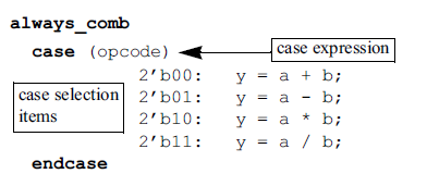
The expression following the case, casex, or casez keyword is referred to as the case expression. The expressions to which the case expression is matched are referred to as the case selection items.
simulation and synthesis might interpret case statements differently
The Verilog standard specifically defines that case statements must evaluate the case selection items in the order in which they are listed. This infers that there is a priority to the case items, the same as in a series of if...else...if decisions. Software tools such as synthesis compilers will typically try to optimize out the additional logic required for priority encoding the selection decisions, if the tool can determine that all of the selection items are mutually exclusive.
SystemVerilog provides special unique and priority modifiers to case, casex, and casez decisions. These modifiers are placed before the case, casex, or casez keywords:
unique case (<case_expression>)
	... // case items
endcase
priority case (<case_expression>)
	... // case items
endcase
7.9.1 Unique case decisions
A unique case statement specifies that:
• Only one case select expression matches the case expression when it is evaluated
• One case select expression must match the case expression when it is evaluated
a unique case can be evaluated in parallel
The unique modifier allows designers to explicitly specify that the order of the case selection items is not significant, and the selections are permitted to be evaluated in parallel. Software tools can optimize out the inferred priority of the selection order. The unique modifier also specifies that the case selection items are complete (or full). Any case expression value that occurs should match one, and only one, case select item. The following example illustrates a case statement where it is obvious that the case selection items are both mutually exclusive and that all possible case select values are specified. The unique keyword documents and verifies that these conditions are true.
always_comb
	unique case (opcode)
		2’b00: y = a + b;
		2’b01: y = a - b;
		2’b10: y = a * b;
		2’b11: y = a / b;
endcase
Checking for unique conditions unique case cannot have overlapping conditions
When a case, casex, or casez statement is specified as unique, software tools must perform additional semantic checks to verify that each of the case selection items is mutually exclusive. If a case expression value occurs during run time that matches more than one case selection item, the tool must generate a run-time warning message.
In the following code snippet, a casez statement is used to allow specific bits of the selection items to be excluded from the comparison with the case expression. When specifying don’t care bits, it is easy to inadvertently specify multiple case selection items that could be true at the same time. In the example below, a casez statement is used to decode which of three bus request signals is active. The designer’s expectation is that the design can only issue one request at a time. The casez selection allows comparing to one specific request bit, and masking out the other bits, which could reduce the gate-level logic needed. Since only one request should occur at a time, the order in which the 3 bits are examined should not matter, and there should never be two case items true at the same time.
logic [2:0] request;
always_comb
	casez (request) // design should only generate one grant at a time
		3’b1??: slave1_grant = 1;
		3’b?1?: slave2_grant = 1;
		3’b??1: slave3_grant = 1;
	endcase
In the preceding example, the casez statement will compile for simulation without an error. If a case expression value could match more than one case selection item (two requests occurred at the same time, for example), then only the first matching branch is executed. No run-time warning is generated to alert the designer or verification engineer of a potential design problem. Though the code in the example above is legal, lint check programs and synthesis compilers will generally warn that there is a potential overlap in the case items. However, these tools have no way to determine if the designer intended to have an overlap in the case select expressions.
The unique modifier documents that the designer did not intend, or expect, that two case select items could be true at the same time. When the unique modifier is added, all software tools, including simulators, will generate a warning any time the case statement is executed and the case expression matches multiple case items.
logic [2:0] request;

always_comb
	unique casez (request) // design should only generate one grant at a time
		3’b1??: slave1_grant = 1;
		3’b?1?: slave2_grant = 1;
		3’b??1: slave3_grant = 1;
endcase
Detecting incomplete case selection lists
a unique case must specify all conditions
When a case, casex, or casez statement is specified as unique, software tools will issue a run-time warning if the value of the case expression does not match any of the case selection items, and there is no default case.
The following example will result in a run-time warning if, during simulation, opcode has a value of 3, 5, 6 or 7:
logic [2:0] opcode; // 3-bit wide vector

always_comb
	unique case (opcode)
		3’b000: y = a + b;
		3’b001: y = a - b;
		3’b010: y = a * b;
		3’b100: y = a / b;
	endcase
Though unique is primarily a run-time check that one, and only one, case select item is true, software tools may report an overlap warning in unique case expression items at compile time, if the case items are all constant expressions. Tools such as synthesis compilers and lint checkers that do not have a dynamic run time can only perform static checks for select item overlaps.
Using unique case with always_comb
Both always_comb and unique case help ensure that the logic of a procedural block can be realized as combinational logic. There are differences in the checks that unique case performs and the checks that always_comb performs. The use of both constructs helps ensure that complex procedural blocks will synthesize as the intended logic.
A unique case statement performs run-time checks to ensure that every case expression value that occurs matches one and only one case selection item, so that a branch of the case statement is executed for every occurring case expression value. An advantage of run-time checking is that only the actual values that occur during simulation will be checked for errors. A disadvantage of run-time checking is that the quality of the error checking is dependent on the thoroughness of the verification tests.
The always_comb procedural block has specific semantic rules to ensure combinational logic behavior during simulation (refer to sections 6.2.1 on page 142). Optionally, software tools can perform additional compile-time analysis of the statements within an always_comb procedural block to check that the statements conform to general guidelines for modeling combinational logic. Having both the static checking of always_comb and the run-time checking of unique case helps ensure that the designer’s intent
has been properly specified.
7.9.2 Priority case statements
A priority case statement specifies that:
• At least one case select expression must match the case expression when it is evaluated
• If more than one case select expression matches the case expression when it is evaluated, the first matching branch must be taken
a priority case might have multiple case item matches
The priority modifier indicates that the designer considers it to be OK for two or more case selection expressions to be true at the same time, and that the order of the case selection items is important.
In the following example, the designer has specified that there is priority to the order in which interrupt requests are decoded, with irq0 having the highest priority.
always_comb
	priority case (1’b1)
		irq0: irq = 4’b0001;
		irq1: irq = 4’b0010;
		irq2: irq = 4’b0100;
		irq3: irq = 4’b1000;
endcase
Because the model explicitly states that case selection items should be evaluated in order, all software tools must maintain the inferred priority encoding, should it be possible for multiple case selection items to match.
NOTE: Synthesis compilers might optimize case selection item evaluation differently than the RTL code, even when priority case is used.
Some synthesis compilers might automatically optimize priority case statements to parallel evaluation if the compiler sees that the case selection items are mutually exclusive. If it is not possible for multiple case selection items to be true at the same time, the additional priority-encoded logic is not required in the gate-level implementation of the functionality.
Preventing unintentional latched logic
a priority case must specify all conditions
When the priority modifier is specified with a case, casex, or casez statement, all values of the case expression that occur during run time must have at least one matching case selection item. If there is no matching case selection item, a run-time warning will occur. This ensures that when the case statement is evaluated, a branch will be executed. The logic represented by the case statement can be implemented as combinational logic, without latches.
7.9.3 Unique and priority versus parallel_case and full_case
The IEEE 1364.1 synthesis standard1 for Verilog specifies special commands, referred to as pragmas, to modify the behavior of synthesis compilers. The 1364.1 pragmas are specified using the Verilog attribute construct. Synthesis compilers also allow pragmas to be hidden within Verilog comments.
synthesis parallel_case pragma
One of the pragmas specified in the Verilog synthesis standard is parallel_case. This instructs synthesis compilers to remove priority encoding, and evaluate all case selection items in parallel.
always_comb
(* synthesis, parallel_case *)
case (opcode)
	2’b00: y = a + b;
	2’b01: y = a - b;
	2’b10: y = a * b;
	2’b11: y = a / b;
endcase
synthesis full_case pragma
Another pragma is full_case. This pragma instructs the synthesis compiler that, for all unspecified case expression values, the outputs assigned within the case statement are unused, and can be optimized out by the synthesis compiler.
always_comb
(* synthesis, full_case *)
case (State)
	3’b001: NextState = 3’b010;
	3’b010: NextState = 3’b100;
	3’b100: NextState = 3’b001;
endcase
unique and priority do more than synthesis pragmas
For synthesis, a unique case is equivalent to enabling both the full_case and parallel_case pragmas. A priority case is equivalent to enabling the full_case pragma. However, the SystemVerilog unique and priority decision modifiers do more than the parallel_case and full_case pragmas. These modifiers reduce the risk of mismatches between software tools, and provide additional semantic checks that can catch potential design problems much earlier in the design cycle.
unique case enforces semantic rules
The unique case modifier combines the functionality of both the parallel_case and full_case pragmas, plus added semantic checking. The 1364.1 Verilog synthesis standard states that the parallel_case pragma will force a parallel evaluation, even if more than one case selection item will evaluate as true. This could result in more than one branch of a case statement executing at the same time. A unique case statement will generate run-time warnings, should the designer’s assumptions that the case statement is both parallel and complete prove incorrect. The parallel_case/ full_case pragmas do not impose any checking on the case selection items.
priority case can prevent mismatches
The priority modifier provides the functionality of the full_case synthesis pragma, plus additional semantic checks. When the full_case pragma is used, no assignment is made to the outputs of the case statement for the unspecified values of the case expression. In RTL simulations, these outputs will be unchanged, and reflect the value of previous assignments. In the gate-level design created by synthesis, the outputs will be driven to some optimized value. This driven value can be, and likely will be, different than the value of the outputs in the RTL model. This difference can result in mismatches between pre-synthesis RTL simulations and post-synthesis gate-level simulations, if an unspecified case expression value is encountered. Equivalence checkers will also see a difference in the two models.
Synthesis pragmas modify how synthesis interprets the Verilog case statements, but they do not affect simulation semantics and might not affect the behavior of other software tools. This can lead to mismatches in how different tools interpret the same case statement. The unique and priority modifiers are part of the language, instead of being an informational synthesis pragma. As part of the language, simulation, synthesis compilers, formal verification tools, lint checkers and other software tools can apply the same semantic rules, ensuring consistency across various tools.
The run-time semantic checks provided by the unique and priority modifiers also help ensure that the logic within a case, casex, or casez statement will behave consistent with the intent specified by the designer. These restrictions can prevent subtle, difficult to detect logic errors within a design.
7.10 Enhanced if...else decisions
The SystemVerilog unique and priority decision modifiers also work with if...else decisions. These modifiers can also reduce ambiguities with this type of decision, and can trap potential design errors early in the modeling phase of a design.
The Verilog if...else statement is often nested to create a series of decisions. For example:
logic [2:0] sel;

always_comb begin
if (sel == 3’b001) mux_out = a;
	else if (sel == 3’b010) mux_out = b;
	else if (sel == 3’b100) mux_out = c;
end
simulation and synthesis might interpret if...else differently
In simulation, a series of if...else...if decisions will be evaluated in the order in which the decisions are listed. To maintain the same ordering in hardware implementation, priority encoded logic would be required. Often, however, the specific order is not essential in the desired logic. The order of the decisions is merely the way the engineer happened to list them in the source code.
7.10.1 Unique if...else decisions
a unique if...else can be evaluated in parallel
The unique modifier indicates that the designer’s intent is that the order of the decisions is not important. Software tools can optimize out the inferred priority of the decision order. For example:
logic [2:0] sel;

always_comb begin
	unique if (sel == 3’b001) mux_out = a;
	else if (sel == 3’b010) mux_out = b;
	else if (sel == 3’b100) mux_out = c;
end
Checking for unique conditions
a unique if...else cannot have overlapping conditions
Software tools will perform checking on a unique if decision sequence to ensure that all decision conditions in a series of if...else...if decisions are mutually exclusive. This allows the decision series to be executed in parallel, without priority encoding. A software tool will generate a run-time warning if it determines that more than one condition is true. This warning message can occur at either compile time or run-time. This additional checking can help detect modeling errors early in the verification of the model.
In the following example, there is an overlap in the decision conditions. Any or all of the conditions for the first, second and third decisions could be true at the same time. This means that the decisions must be evaluated in the order listed, rather than in parallel. Because the unique modifier was specified, software tools can generate a warning that the decision conditions are not mutually exclusive.
logic [2:0] sel;
always_comb begin
	unique if (sel[0]) mux_out = a;
	else if (sel[1]) mux_out = b;
	else if (sel[2]) mux_out = c;
end
Preventing unintentional latched logic
a unique if...else warns of unspecified conditions
When the unique modifier is specified with an if decision, software tools are required to generate a run-time warning if the if statement is evaluated and no branch is executed. The following example would generate a run-time warning if the unique if...else...if sequence is entered and sel has any value other than 1, 2 or 4.
always_comb begin
	unique if (sel == 3’b001) mux_out = a;
	else if (sel == 3’b010) mux_out = b;
	else if (sel == 3’b100) mux_out = c;
end
This run-time semantic check guarantees that all conditions in the decision sequence that actually occur during run time have been fully specified. When the decision sequence is evaluated, one branch will be executed. This helps ensure that the logic represented by the decisions can be implemented as combinational logic, without the need for latches.
7.10.2 Priority if decisions
a priority if...else must evaluate in order
The priority modifier indicates that the designer’s intent is that the order of the decisions is important. Software tools should maintain the order of the decision sequence. For example:
always_comb begin
	priority if (irq0) irq = 4’b0001;
	else if (irq1) irq = 4’b0010;
	else if (irq2) irq = 4’b0100;
	else if (irq3) irq = 4’b1000;
end
Because the model explicitly states that the decision sequence above should be evaluated in order, all software tools should maintain the inferred priority encoding. The priority modifier ensures consistent behavior from software tools. Simulators, synthesis compilers, equivalence checkers, and formal verification tools can all interpret the decision sequence in the same way.
Preventing unintentional latched logic
a priority if...else must specify all conditions
As with the unique modifier, when the priority modifier is specified with an if decision, software tools will perform run-time checks that a branch is executed each time an if...else...if sequence is evaluated. A run-time warning will be generated if no branch of a priority if...else...if decision sequence is executed. This helps ensure that all conditions in the decision sequence that actually occur during run time have been fully specified, and that when the decision sequences are evaluated, a branch will be executed. The logic represented by the decision sequence can be implemented as priority-encoded combinational logic, without latches.
Synthesis guidelines
An if...else...if decision sequence that is qualified with unique or priority is synthesizable.
A primary goal of SystemVerilog is to enable modeling large, complex designs more concisely than was possible with Verilog. This chapter presented enhancements to the procedural statements in Verilog that help to achieve that goal. New operators, enhanced for loops, bottom-testing loops, and unique/priority decision modifiers all provide new ways to represent design logic with efficient, intuitive code.
- SystemVerilog Chapter Edition Design forsystemverilog chapter edition design systemverilog catalog edition design solutions edition chapter primer systemverilog systemverilog接口 systemverilog第一次logic 数组systemverilog systemverilog randomization dynamic array systemverilog模板vscode systemverilog xilinx vivado 2020