一、参考资料
1、Coordinate System Qt官方文档
2、小谈Qt的坐标系系统 - 3个坐标系,2个变换 - 知乎 (zhihu.com)
3、提示:第二部分为官方文档,第三部分为精通。如果您只想理解坐标系之间的转换,请移步第三部分。如果需要一些更加详细的内容,请仔细研读第二部分。
二、Qt的坐标系系统
The coordinate system is controlled by the QPainter class. Together with the QPaintDevice and QPaintEngine classes, QPainter form the basis of Qt's painting system, Arthur. QPainter is used to perform drawing operations, QPaintDevice is an abstraction of a two-dimensional space that can be painted on using a QPainter, and QPaintEngine provides the interface that the painter uses to draw onto different types of devices.
坐标系统由QPainter类控制。它和QPaintDevice和QPaintEngine类一起构成Qt绘图系统的基础。QPainter用于执行绘图操作,QPaintDevice是QPainter用来绘制的一个二维空间的抽象,QPaintEngine提供在不同设备绘图的接口。
The QPaintDevice class is the base class of objects that can be painted: Its drawing capabilities are inherited by the QWidget, QImage, QPixmap, QPicture, and QOpenGLPaintDevice classes. The default coordinate system of a paint device has its origin at the top-left corner. The x values increase to the right and the y values increase downwards. The default unit is one pixel on pixel-based devices and one point (1/72 of an inch) on printers.
QPaintDevice类是可以被绘制的对象的基类:它的绘制能力被QWidget、QImage、QPixmap、QPicture和QOpenGLPaintDevice类继承。绘制设备的默认坐标系统的原点位于左上角。x值向右增加,y值向下增加。在基于像素的设备上,默认单位是一个像素,在打印机上是一个点(1/72英寸)。
The mapping of the logical QPainter coordinates to the physical QPaintDevice coordinates are handled by QPainter's transformation matrix, viewport and "window". The logical and physical coordinate systems coincide by default. QPainter also supports coordinate transformations (e.g. rotation and scaling).
逻辑QPainter坐标到物理QPaintDevice坐标的映射是由QPainter的变换矩阵、视口和“窗口”处理的。默认情况下,逻辑和物理坐标系统是一致的。QPainter还支持坐标转换(例如旋转和缩放)。
1、Rendering渲染
1.1 图像的逻辑表示
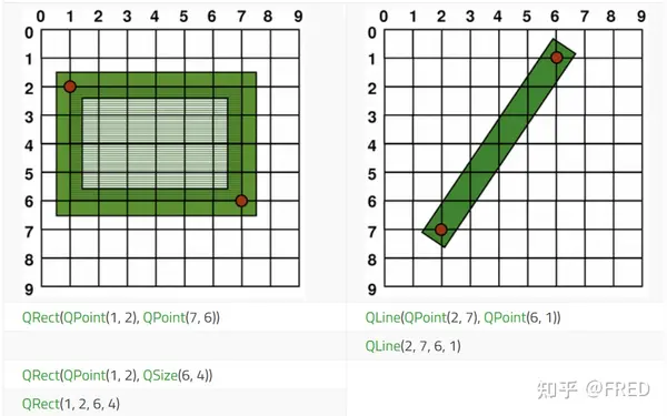
The size (width and height) of a graphics primitive always correspond to its mathematical model, ignoring the width of the pen it is rendered with:
图形的几何尺寸只是对应它的数学模型,忽略了渲染(绘制时)的笔宽。请注意右边这条斜线,一个格子就是显示器所能显示的一个像素,每一个格子里面只能显示一个颜色,并且是不能分割的。所以这个图是一个几何尺寸,实际在屏幕上的显示不是这样的。
1.2 Aliased Painting锯齿绘图
When drawing, the pixel rendering is controlled by the QPainter::Antialiasing render hint.
绘图时,像素渲染由QPainter::Antialiasing渲染提示来控制。
The RenderHint enum is used to specify flags to QPainter that may or may not be respected by any given engine. The QPainter::Antialiasing value indicates that the engine should antialias edges of primitives if possible, i.e. smoothing the edges by using different color intensities.
渲染提示枚举用于指定QPainter的标志,这些标志可能被任何给定的引擎尊重,也可能不被尊重。QPainter::Antialiasing值表示引擎应该尽可能地消除原语的边缘,即通过使用不同的颜色强度平滑边缘。一言蔽之,渲染引擎会尽量考虑这个反锯齿标志,但是不是所有的渲染引擎都支持。
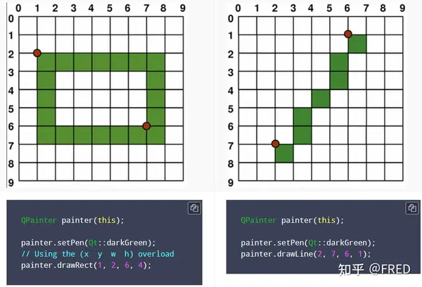
But by default the painter is aliased and other rules apply: When rendering with a one pixel wide pen the pixels will be rendered to the right and below the mathematically defined points. For example:
但是缺省的绘图是被如下渲染规则控制:当使用一个像素宽的笔渲染时,像素将被渲染到右边,并低于数学定义的点。例如:
When rendering with a pen with an even number of pixels, the pixels will be rendered symmetrically around the mathematical defined points, while rendering with a pen with an odd number of pixels, the spare pixel will be rendered to the right and below the mathematical point as in the one pixel case. See theQRectFdiagrams below for concrete examples.
当使用具有偶数像素的笔进行渲染时,像素将围绕数学定义的点对称地渲染,而使用具有奇数像素的笔进行渲染时,多余的像素将像在一个像素的情况下一样呈现在数学点的右侧和下方。有关具体示例,请参见下面的qrectfdiagrams。
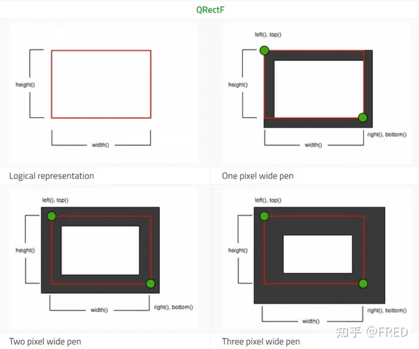
Note that for historical reasons the return value of the QRect::right() and QRect::bottom() functions deviate from the true bottom-right corner of the rectangle.
请注意,由于历史原因,QRect::right()和QRect::bottom()函数的返回值偏离了矩形的真正右下角。
QRect's right() function returns left() + width() - 1 and the bottom() function returns top() + height() - 1. The bottom-right green point in the diagrams shows the return coordinates of these functions.
QRect的right()函数返回left() + width() - 1, bottom()函数返回top() + height() - 1。图中右下角的绿色点表示这些函数的返回坐标。
We recommend that you simply use QRectF instead: The QRectF class defines a rectangle in the plane using floating point coordinates for accuracy (QRect uses integer coordinates), and the QRectF::right() and QRectF::bottom() functions do return the true bottom-right corner.
我们建议您简单地使用QRectF来代替:QRectF类使用浮点坐标在平面中定义一个矩形以保证精度(QRect使用整数坐标),并且QRectF::right()和QRectF::bottom()函数返回真正的右下角。
Alternatively, using QRect, apply x() + width() and y() + height() to find the bottom-right corner, and avoid the right() and bottom() functions.
或者,使用QRect,应用x() + width()和y() + height()来查找右下角,并避免使用right()和bottom()函数。
1.3 Anti-aliased Painting反锯齿绘图
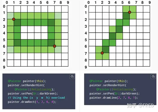
If you set QPainter's anti-aliasing render hint, the pixels will be rendered symmetrically on both sides of the mathematically defined points:
如果你设置QPainter的反锯齿渲染提示,像素将在数学定义的点的两侧对称渲染:效果如下。
2、Transformations 坐标转换
By default, the QPainter operates on the associated device's own coordinate system, but it also has complete support for affine coordinate transformations.
默认情况下,QPainter在相关设备自己的坐标系统上操作,但它也完全支持仿射坐标转换。
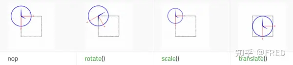
You can scale the coordinate system by a given offset using the QPainter::scale() function, you can rotate it clockwise using the QPainter::rotate() function and you can translate it (i.e. adding a given offset to the points) using the QPainter::translate() function.
你可以使用QPainter::scale()函数按给定的参数缩放坐标系,你可以使用QPainter::rotate()函数顺时针旋转它,你可以使用QPainter::translate()函数平移它(即向点添加给定的偏移量)。
You can also twist the coordinate system around the origin using the QPainter::shear() function. All the transformation operations operate on QPainter's transformation matrix that you can retrieve using the QPainter::worldTransform() function. A matrix transforms a point in the plane to another point.
您还可以使用QPainter::shear()函数在原点周围扭转(可以理解为x y坐标不再是正交)坐标系统。所有的转换操作都可以通过QPainter的转换矩阵进行操作,您可以使用QPainter::worldTransform()函数检索这些转换矩阵。矩阵将平面上的一个点变换为另一个点。
If you need the same transformations over and over, you can also use QTransform objects and the QPainter::worldTransform() and QPainter::setWorldTransform() functions. You can at any time save the QPainter's transformation matrix by calling the QPainter::save() function which saves the matrix on an internal stack. The QPainter::restore() function pops it back.
如果您需要反复进行相同的转换,您还可以使用QTransform对象和QPainter::worldTransform()和QPainter::setWorldTransform()函数。您可以在任何时候通过调用QPainter::save()函数保存QPainter的变换矩阵,该函数将矩阵保存在内部堆栈上。QPainter::restore()函数将其弹出。
One frequent need for the transformation matrix is when reusing the same drawing code on a variety of paint devices. Without transformations, the results are tightly bound to the resolution of the paint device. Printers have high resolution, e.g. 600 dots per inch, whereas screens often have between 72 and 100 dots per inch.
变换矩阵的一个常见需求是在不同的绘图设备上重用相同的绘图代码。如果没有转换,结果将与绘制设备的分辨率紧密绑定。打印机具有高分辨率,例如每英寸600点,而屏幕通常在每英寸72到100点之间。
For more information about the transformation matrix, see theQTransformdocumentation.
转换矩阵更多信息,详见QTransform文档。
3、Window-Viewport Conversion 窗口-视口转换
When drawing with QPainter, we specify points using logical coordinates which then are converted into the physical coordinates of the paint device.
当使用QPainter绘图时,我们使用逻辑坐标指定点,然后将其转换为绘制设备的物理坐标。
The mapping of the logical coordinates to the physical coordinates are handled by QPainter's world transformation worldTransform() (described in the Transformations section), and QPainter's viewport() and window(). The viewport represents the physical coordinates specifying an arbitrary rectangle. The "window" describes the same rectangle in logical coordinates. By default the logical and physical coordinate systems coincide, and are equivalent to the paint device's rectangle.
逻辑坐标到物理坐标的映射是由QPainter的世界变换worldTransform()(在变换部分描述)和QPainter的viewport()和window()处理的。视口表示指定任意矩形的物理坐标。“窗口”在逻辑坐标中描述相同的矩形。默认情况下,逻辑和物理坐标系统是重合的,并且与绘制设备的矩形相等。
Using window-viewport conversion you can make the logical coordinate system fit your preferences. The mechanism can also be used to make the drawing code independent of the paint device. You can, for example, make the logical coordinates extend from (-50, -50) to (50, 50) with (0, 0) in the center by calling the QPainter::setWindow() function:
使用窗口-视口转换,您可以使逻辑坐标系统符合您的偏好。这种机制还可用于使所述绘图代码独立于绘图设备。例如,你可以通过调用QPainter:: setwinwindow()函数,使窗口的逻辑坐标从(-50,-50)扩展到(50,50),中间是(0,0):
QPainter painter(this);
painter.setWindow(QRect(-50, -50, 100, 100));
Now, the logical coordinates (-50,-50) correspond to the paint device's physical coordinates (0, 0). Independent of the paint device, your painting code will always operate on the specified logical coordinates.
现在,逻辑坐标(-50,-50)对应于绘制设备的物理坐标(0,0)。独立于绘制设备,您的绘制代码将始终对指定的逻辑坐标进行操作。
By setting the "window" or viewport rectangle, you perform a linear transformation of the coordinates. Note that each corner of the "window" maps to the corresponding corner of the viewport, and vice versa. For that reason it normally is a good idea to let the viewport and "window" maintain the same aspect ratio to prevent deformation:
通过设置“窗口”或视口矩形,可以执行坐标的线性变换。请注意,“窗口”的每个角落都映射到viewport的相应角落,反之亦然。出于这个原因,让视口和“窗口”保持相同的宽高比 是防止变形的好主意:
int side = qMin(width(), height());
int x = (width() - side / 2);
int y = (height() - side / 2);

painter.setViewport(x, y, side, side);
If we make the logical coordinate system a square, we should also make the viewport a square using the QPainter::setViewport() function. In the example above we make it equivalent to the largest square that fit into the paint device's rectangle. By taking the paint device's size into consideration when setting the window or viewport, it is possible to keep the drawing code independent of the paint device.
如果我们将逻辑坐标系统设置为正方形,我们也应该使用QPainter::setViewport()函数将视口设置为正方形。在模拟时钟的例子中,我们将其设置为适合绘制设备矩形的最大正方形。通过在设置窗口或视口时考虑绘制设备的大小,可以保持绘制代码独立于绘制设备。
Note that the window-viewport conversion is only a linear transformation, i.e. it does not perform clipping. This means that if you paint outside the currently set "window", your painting is still transformed to the viewport using the same linear algebraic approach.
注意,窗口-视口转换只是一个线性转换,即它不执行裁剪。这意味着如果你在当前设置的“窗口”之外绘制,你的绘画仍然会使用相同的线性代数方法转换到视口。这句话的意思是绘制在窗口外面(比如点(-10,-10))如果转化后在视口内的话,它仍然会绘制出来,窗口不会裁剪掉窗口外的内容。

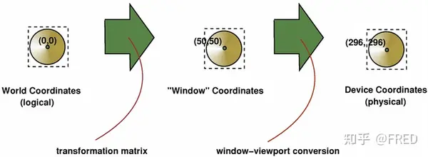
The viewport, "window" and transformation matrix determine how logical QPainter coordinates map to the paint device's physical coordinates. By default the world transformation matrix is the identity matrix, and the "window" and viewport settings are equivalent to the paint device's settings, i.e. the world, "window" and device coordinate systems are equivalent, but as we have seen, the systems can be manipulated using transformation operations and window-viewport conversion. The illustration above describes the process.
视口、“窗口”和变换矩阵决定了QPainter 逻辑坐标如何映射到绘制设备的物理坐标。默认情况下,世界变换矩阵是单位矩阵(矩阵对角线位置都是1,其他都是0),“窗口”和视口设置对于绘制设备的设置是等同的,即世界、“窗口”和设备坐标系是等效的,但正如我们所看到的,系统可以使用<转换操作>和<窗口-视口转换>来操纵。上面的插图描述了这个过程。
See also参见 Analog Clock. 模拟时钟程序示例。(本文章删除了该例程内容。)
三、Qt坐标系统精通
1、坐标系概念
坐标系的中文名称多且并不统一,主要源于翻译过程。从上文Qt坐标系统文档可以看出,Qt并没有划分几类坐标系,而是直接使用了“coordinate system”坐标系统一词。
绘图设备的缺省坐标系统原点位于左上角,x值向右为正,y值向下为负。如上文第一部分指出的那样:QPainter控制这个坐标系,并依据这个坐标系绘制。我们暂且把它称之为“逻辑坐标系”。
1.1 逻辑坐标系
逻辑坐标系有时候也被称之为世界坐标系、用户坐标系,它表现的是用户数据的坐标关系。例如:做城市规划工作的小李规划一块教育用地,这块地形状是梯形,它的四个顶点的坐标是:
QPoint p1 = (100,100);
QPoint P2 = (100,2000);
QPoint p3 = (3000,2000);
QPoint p4 = (3000,400);
这些点的坐标就是这块梯形土地的四个顶点坐标,小李知道它们的单位是米,并且形状是下面这个样子的:
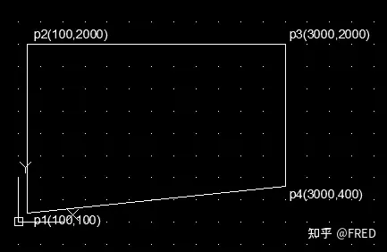
注意,在小李这里,他是认为左下角是原点(0,0),x向右为正,y向上为正。这是他在纸上画出来的图,上北下南。小李把所有的数据都存到了数据库里面,这是这块地的规划数据和他所期望展现的图形。
随着数字化的进程,小李作为一个程序员爱好者,选择了好用的Qt作为开发平台。
1.2 程序处理。
小李建立了一个基于QWidget的程序,没有带ui界面。因为他需要在窗口上绘制这块地形。他建立的程序代码如下:
//widget.h文件
#ifndef WIDGET_H
#define WIDGET_H

#include <QWidget>
#include <QPainter>

class Widget : public QWidget
{
    Q_OBJECT

public:
    Widget(QWidget *parent = nullptr);
    ~Widget();

    void paintEvent(QPaintEvent *event);
};
#endif // WIDGET_H
.h文件如上,.cpp文件如下
//widget.cpp文件
#include "widget.h"

Widget::Widget(QWidget *parent)
    : QWidget(parent)
{
    resize(500,500);
}

Widget::~Widget()
{
}

void Widget::paintEvent(QPaintEvent *event)
{
    QPainter painter(this);
    QPoint p1 = QPoint(100,100);
    QPoint p2 = QPoint(100,2000);
    QPoint p3 = QPoint(3000,2000);
    QPoint p4 = QPoint(3000,400);
    painter.drawLine(p1, p2);
    painter.drawLine(p2, p3);
    painter.drawLine(p3, p4);
    painter.drawLine(p4, p1);

}
运行后程序的程序窗口显示为如下:
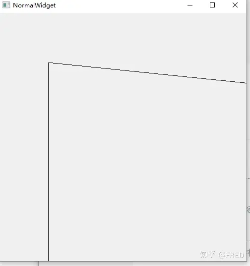
为什么会这样呢?小李思考一下,觉得可能是以下原因造成的,并想出了解决的办法:
这个图形从这个角来看,是把图形上下颠倒绘制了。
程序中的窗口太小,无法全部显示这块地的全貌。
解决方法:买一块足够显示这块地的显示器,然后把 resize(500,500)改为resize(3000,3000)。至于上下颠倒的问题,只能倒着看显示器了。
亲爱的朋友们,你们觉得小李这个解决方法对不对?欢迎在评论区留言。
1.3 窗口坐标
小李的解决方案因为需要耗费的资金太大,无法实施。因为还有很多面积更大的地,这个方法行不通。
好在小李的女朋友告诉小李应该上知乎上寻找以下答案。小李通过知乎查找和F1键翻阅Qt帮助文件,找到了一个方法。他发现只要在paintEvent函数中添加一句代码就可以了:
void Widget::paintEvent(QPaintEvent *event)
{
    QPainter painter(this);
    QPoint p1 = QPoint(100,100);
    QPoint p2 = QPoint(100,2000);
    QPoint p3 = QPoint(3000,2000);
    QPoint p4 = QPoint(3000,400);
    painter.setWindow(0,0,4000,4000); //添加这行代码
    painter.drawLine(p1, p2);
    painter.drawLine(p2, p3);
    painter.drawLine(p3, p4);
    painter.drawLine(p4, p1);

}
程序再次运行后,终于全部显示了这块地,虽然还是上下颠倒了。知道了这条命令,小李从此再不怕地块大了。他也开始涉足大面积土地规划开发,从此开始了自己辉煌的生活。

通过不断探索Qt帮助文件,小李终于找到了一个办法,让图形上下不再颠倒。原来还是很简单:
只要在paintEvent函数中把上面那句代码修改如下就可以了!
//    painter.setWindow(0,0,4000,4000); //添加这行代码
    painter.setWindow(0,4000,4000,-4000); //修改为这行代码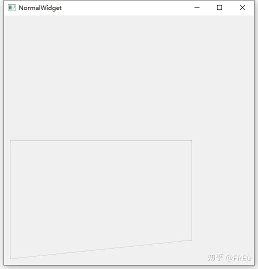
看到这个画面,小李泪流满面。终于绘制出了方向正确,且完全包括这个地块的图形了。
各位看官,您是否也有如此感动呢?
2、逻辑坐标系和窗口坐标系总结
2.1 看到这里,想必已经对逻辑坐标系和窗口坐标系有了一个感性认识。特别提问如下:
(1)这块地的逻辑坐标变了吗?——没有。地是不动产,它的位置是固定的。所以小李这里采用的逻辑坐标系(数据)在绘制过程是不会发生变化的。
(2)窗口变大了吗?——也没有。但是窗口能容纳的区域好像变大了(其实,也没有。窗口还是500*500像素的正方形窗口。有些人把
//    painter.setWindow(0,0,4000,4000); //添加这行代码
    painter.setWindow(0,4000,4000,-4000); //修改为这行代码
这行代码执行后的窗口认为其也有一个坐标,命名之为“窗口坐标”。
窗口坐标在这句代码之前,它是和逻辑坐标100%完全重合的。当小李用QPainter绘图时,它也是严格按照1:1比例和缺省的方向进行绘制,超出窗口的部分无法显示了。
通过这句代码,不但让窗口显示的更多(也可以更少),也能上下颠倒(还能旋转和偏移、扭曲等操作)。就可以在窗口中对图形进行转换。
在AutoCAD中,坐标系有绝对坐标系和相对坐标系。我们可以理解逻辑坐标系就是绝对坐标系(世界坐标系),相对坐标系类似窗口坐标系。
为了统一期间:建议大家称之为:
【世界坐标系】、【窗口坐标系】,前者是固定不变的,后者是相对的。
世界坐标系转换到窗口坐标系采用函数 setWindow()函数。窗口左边系一般不会转换为世界坐标系,因为原始数据一般不会因为显示的需求而进行修改。当然如果你在开发交互式程序,比如小李希望能在程序中修改这块地的数据,它希望用鼠标来修改。当他获取鼠标鼠标时,他得到的鼠标基于窗口的坐标范围是[0..500],并且是原点窗口在左上角。此时他就需要将窗口坐标系转换为世界坐标系来更新原始数据。
至于坐标系之间的来回切换,大家可以查找QTransform文档。这里不再赘述。
2.2 setWindows()函数详解
setWindows()函数有以下两种形式,其参数一种是矩形,一种是提供了原点x y和矩形的宽、高。功能是一样的。
void QPainter::setWindow(const QRect &rectangle)
void QPainter::setWindow(int x, int y, int width, int height)
Sets the painter's window to the given rectangle, and enables view transformations.
The window rectangle is part of the view transformation. The window specifies the logical coordinate system. Its sister, the viewport(), specifies the device coordinate system.
The default window rectangle is the same as the device's rectangle.
其简介为:设置绘图窗口到给定的矩形,并打开视口转换。窗口矩形是视口转换的一部分。这个窗口指定了逻辑坐标系统。它的姊妹函数viewport()指定了设备坐标系统。缺省情况下,窗口矩形和设备矩形是一致的。
再说一下个人理解:
(1)窗口的坐标本例子中左上角为(0,0),右下角为(500,500)这个在windows系统中是没有任何变化,这个程序的窗口总是占据500像素宽高的大小。此时,如果我们通过其他方法获取鼠标在窗口的坐标它的范围仍然是以这个像素范围返回鼠标位置的。
(2)setWindows()函数指定了这个窗口的逻辑坐标系统,这个逻辑坐标系统是用来把窗口的像素坐标和世界坐标之间建立一个映射。这种映射,不但可以偏移、还可以旋转、反转、缩放、扭曲(这些统称为坐标转换)。
在进一步理解前,我们先说一个自己总结的定律:
【任何一个平面直角坐标系,x坐标和y坐标都不相同的两个点可以确定一个坐标系统。】这条定律也是为什么使用setWindows()函数时,只要输入一个矩形(左上角、宽高)就相当于指定了这样两个点。
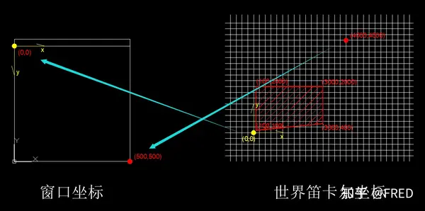
我们第一次用的"painter.setWindow(0,0,4000,4000); "这个函数的图形几何概念就如上图。我们窗口有一个坐标系系统(左上角为0,0,右下角为500,500),通过这句代码,我们让窗口坐标的黄色点坐标(0,0)和世界笛卡尔坐标系的点(0,0)对应起来,让窗口坐标(500,500)和世界笛卡尔坐标系的点(4000,4000)对应起来。
因为两个坐标系y轴的方向是不一致的,所以映射过来后,这块地的图形就上下颠倒了。
所以:setWindows()函数的前两个参数就是窗口左上角对应的其他需要映射的图形需要显示在左上角的一个点,后两个参数是屏幕右小角对应其他需要映射的图形需要显示在右下角的另外一个点。因为在平面直角坐标系下,两个点就可以确定一个坐标系统,所以通过这两个点就把这两个坐标系映射起来了。注意参数的第一个和第三个,第二个和第四个必须不同!并且第二点为第一点的相对坐标!
这里是因为我们用现实中的笛卡尔坐标系,所以存在上下翻转问题,如果两个坐标系方向都是一致的,图形就不会反转。
painter.setWindow(0,4000,4000,-4000)可以直接反转笛卡尔坐标系,其几何概念如下图:
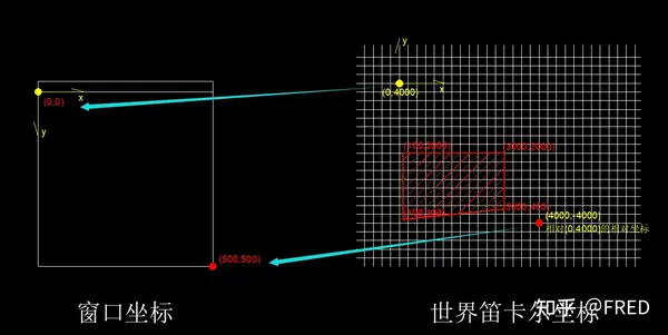
前两个参数(0,4000)就是对应窗口左上角的世界笛卡尔坐标,右下角的坐标为笛卡尔坐标系里面相对第一个点的相对坐标(这一点和函数说明是一致的int x, int y, int width, int height)。这样映射后,程序窗口的左上角就在世界笛卡尔坐标系的(0,4000),右下角在世界笛卡尔坐标系的(4000,0绝对坐标),但是输入右下角坐标时【一定】注意输入的是“相对坐标”。
另外在这个映射过程中x y坐标也可以不是相同的比例、也可以进行其他转化。转化可以直接计算,也可以用矩阵进行正向和逆向计算。这些,大家可以自行在程序里面试着变化这个参数来体验。窗口坐标系理解清楚了基本可以解决大部分图形显示中遇到的问题。
至此,窗口坐标系就说明结束了。如果您喜欢,还请多多支持。
3、设备坐标系Device Coordinates
3.1 设备坐标系和屏幕
设备坐标系是基于具体的硬件设备的。其实对于我们来说常用的设备坐标系就是打印机和屏幕。
我们再理解一下这个图,当我们绘制一个圆形在(0,0)的圆时,我们实在一个逻辑坐标系中。但是如果我们希望在一个程序窗口中绘制这个圆时,如果我们把圆心还是绘制在(0,0),那我们就只能看见1/4个圆(如果这句话您还不明白,就需要再重新研学前面内容)。所以我们希望窗口的(0,0)不是前面的左上角,而是在程序窗口的中间,这时候就需要通过setWindows()函数来调整。
我们将“widget.cpp"文件内容修改如下
// widget.cpp
#include "widget.h"
Widget::Widget(QWidget *parent)
: QWidget(parent)
{
resize(200,200);
}
Widget::~Widget()
{
}
void Widget::paintEvent(QPaintEvent *event)
{
QPainter painter(this);
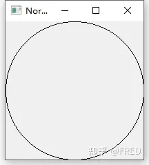
painter.drawEllipse(QPoint(0,0),100,100); //这种绘制椭圆的方式是,第一个参数的点坐标表示椭圆心,后面两个表示轴长。
}运行结果如下图:
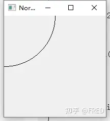
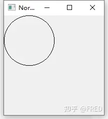
注意,这个圆只绘制了1/4。如果我们不想修改绘制椭圆的参数,但还要圆形显示到程序窗口里面。我们就可以使用setWindow()函数。这里我们采用了利用窗口的长和宽来计算setWindws()的参数,修改后代码如下:
void Widget::paintEvent(QPaintEvent *event)
{
    QPainter painter(this);
    painter.setWindow(-width()/2, -height()/2, width(), height()); //添加这行代码
    painter.drawEllipse(QPoint(0,0),100,100);
}
这时候窗口的左上角对应(-100,-100),右下角对应(100,100)。width()的值为200,height()的值也是200。可以理解窗口坐标是圆心在窗口中心,x向右为正,y向下为正的一个窗口坐标系。可以看出来,我们绘制圆形仍然采用圆点(0,0),但是圆的中心仍然绘制到了窗口的中心。
这里注意对于长宽比不同的窗口要注意采用相同的比例,这里不再详细说明。
3.2 视口和窗口
在上面的例子中,我们并没有用到窗口坐标和视口坐标的转换,但是我们已经解决我们的大部分需求。我们利用setWindows()设置了窗口坐标后,这时候,窗口坐标和视口坐标是相同的。
这里我们去掉setWindows,来看看setViewport函数在不同参数下的效果
void Widget::paintEvent(QPaintEvent *event)
{
    QPainter painter(this);
    painter.setViewport(0, 0, width()/2, height()/2); //效果1
    painter.setViewport(0, 0, width(), height()); //效果2
    painter.setViewport(0, 0, width()*2, height()*2); //效果3
    painter.drawEllipse(QPoint(0,0),100,100);
}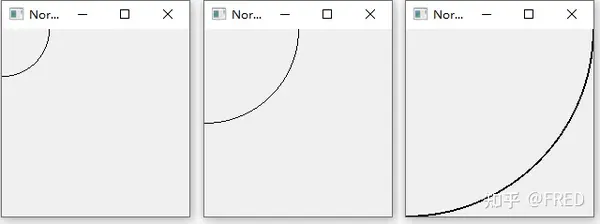
我们通过setViewport()函数设置不同的参数,生成不同效果来看setViewport函数的效果。和前面对比,可以看出效果2这行代码和没有setViewport()这一句的效果是一样的。主要特点如下:
(1)setViewport的参数如果如果是程序窗口的参数,没有效果;
(2)参数框定的范围如果起点不变,会基于起点对图形进行缩放(包括线宽);
void Widget::paintEvent(QPaintEvent *event)
{
    QPainter painter(this);
    painter.setViewport(50, 50, width()/2, height()/2); //添加这行代码
    painter.drawEllipse(QPoint(0,0),100,100);
}
参数修改后还可以得到这个效果,可以看出来setViewport的前两个参数相当于在窗口中设置了圆点坐标,而后两个坐标则可以控制缩放来起到类似焦距调整的效果。
setWindows()和setViewport()都可以控制图形在窗口的显示效果,但是其偏重点显然是不一样的。setWindows更偏重于图形几何坐标和窗口坐标建立映射,可以调整坐标系,使其对应起来。这里主要使点坐标的对应关系。而setViewport更偏向于如何“看”窗口的图形,通过偏移和远近关系,来从不同的位置来看图形的效果。因为其同时可以缩放线宽,所以可以和物理设备对应来,达到达到准确绘制的效果。
这两个函数经常同时使用,其效果也是叠加的。有些显示效果,这两个函数有时候都能满足。所以个人理解这两个函数并不是三个坐标系之间的固定转换,问一个扰乱你的问题:
“setViewport()修改视口坐标时,窗口坐标变化吗?”——这是一个操蛋的问题。因为你没有使用setWindows来修改程序窗口的窗口坐标,但是如果从图形的逻辑坐标来看,应该也是改变了。但是我们没有使用setWindows进行逻辑坐标和窗口坐标的转化啊!?
所以,个人理解还是应该从应用来理解:setWindows()来设置窗口,必须前面用到的坐标系上下颠倒。而视口更多用于窗口的平移和缩放,便于绘制。而QPainter的 translate()函数的转化是绘图坐标系的转化,利用相对坐标的便利性快捷绘图。
看到这里的您,如果希望进一步研究,建议研究实验方向如下:
(1)setWindows使用x y不同的比值的映射;
(2) 尝试解决x轴和y轴非正交情况下应该如何设置(不修改逻辑数据)
最后,感谢您的浏览。并请给予最大的帮助!
from:https://www.zhihu.com/tardis/zm/art/634951149?source_id=1005#:~:text=%E4%BA%8C%E3%80%81Qt%E7%9A%84%E5%9D%90%E6%A0%87%E7%B3%BB%E7%B3%BB%E7%BB%9F%201%201%E3%80%81Rendering%E6%B8%B2%E6%9F%93%201.1%20%E5%9B%BE%E5%83%8F%E7%9A%84%E9%80%BB%E8%BE%91%E8%A1%A8%E7%A4%BA%20...%202%202%E3%80%81Transformations,coordinate%20transformations.%20...%203%203%E3%80%81Window-Viewport%20Conversion%20%E7%AA%97%E5%8F%A3-%E8%A7%86%E5%8F%A3%E8%BD%AC%E6%8D%A2%20