原文:https://zhuanlan.zhihu.com/p/380205701?utm_id=0
全彩屏的使用
1. SPI 显示屏(控制器 ST7735S)的介绍;
2. 显示屏的常用 API;
3. 循迹状态的本地 (显示屏)、远程 (WiFi)
实时显示;
4. 扩展测试及日报编写
学习路径
1、学习了解全彩屏的基本概念,了解程序员眼中的全彩屏;
2、了解LED彩屏常用的驱动芯片;
3、实验用的LCD驱动芯片为ST7735S,查找阅读相关的Arduino函数库;
4、移植函数库到RPI Pico上;
5、将ST7735S彩屏用到自己的项目中。
显示屏连接要点
#define TFT_CS 22
#define TFT_RST 7 // Or set to -1 and connect to Arduino RESET pin
#define TFT_DC 2
#define TFT_SDA 20
#define TFT_SCL 21
#define TFT_BL 19
彩屏


当前的液晶屏有一个指标叫分辨率,就是在微观层面,我们看的手机、显示器实际上的内容实际上是由一个一个的小方块组成的,这些小方块在比较远的位置看,就突显不出来了,再经过大脑的处理,就形成了连续的图像。,
每一个小图块就是像素,每一个像素就有自己的颜色。在计算机领域这个颜色常用RGB色彩描述。RGB色彩模式是工业界的一种颜色标准,是通过对红(R)、绿(G)、蓝(B)三个颜色通道的变化以及它们相互之间的叠加来得到各式各样的颜色的,RGB即是代表红、绿、蓝三个通道的颜色,这个标准几乎包括了人类视力所能感知的所有颜色,是目前运用最广的颜色系统之一。
LCD屏幕的发光原理主要依靠背光层,背光层发出白光,背光层上有一层有颜色的薄膜,透过薄膜之后就能显示出彩色,在背光层和颜色薄膜之间液晶层,调整红蓝绿的比例。
这个RGB的比例,有多种表达方式,常见的有RGB555、RGB565、RGB24和RGB32。
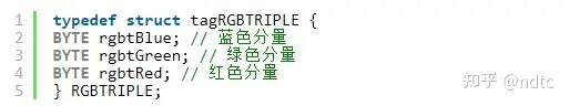
RGB24使用24位来表示一个像素,RGB分量都用8位表示,取值范围为0-255。注意在内存中RGB各分量的排列顺序为:BGR BGR BGR…。通常可以使用RGBTRIPLE数据结构来操作一个像素,它的定义为:
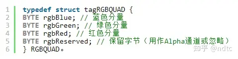
RGB32使用32位来表示一个像素,RGB分量各用去8位,剩下的8位用作Alpha通道或者不用。(ARGB32就是带Alpha通道的RGB24。)注意在内存中RGB各分量的排列顺序为:BGRA BGRA BGRA…。通常可以使用RGBQUAD数据结构来操作一个像素,它的定义为:
了解了上述内容之后,我们可以知道,在程序员眼里的显示屏实际上就是一个二维数组,这个数组的每一个元素就是一个像素。改变这个二维数组的元素的值,就改变了对应的像素的颜色,改变一系列像素的值,就形成了线条、图案。
移植的例程参考
下面给出了一个笔者搜索到的Adafruit提供的SPI显示屏例程并适配到RPI Pico上的结果,大家可以根据里面的内容(包括头文件、函数名)在网上尝试搜索并构建一个可工作的demo。
//
#include <Adafruit_GFX.h> // Core graphics library
#include <Adafruit_ST7735.h> // Hardware-specific library for ST7735
#include <Adafruit_ST7789.h> // Hardware-specific library for ST7789
#include <SPI.h>

// For the breakout board, you can use any 2 or 3 pins.
// These pins will also work for the 1.8" TFT shield.
#define TFT_CS 22
#define TFT_RST 7 // Or set to -1 and connect to Arduino RESET pin
#define TFT_DC 2
#define TFT_SDA 20
#define TFT_SCL 21
#define TFT_BL 19

// OPTION 1 (recommended) is to use the HARDWARE SPI pins, which are unique
// to each board and not reassignable. For Arduino Uno: MOSI = pin 11 and
// SCLK = pin 13. This is the fastest mode of operation and is required if
// using the breakout board's microSD card.

// For 1.44" and 1.8" TFT with ST7735 use:
//Adafruit_ST7735(int8_t cs, int8_t dc, int8_t mosi, int8_t sclk, int8_t rst);
Adafruit_ST7735 tft = Adafruit_ST7735(TFT_CS, TFT_DC, TFT_SDA, TFT_SCL, TFT_RST);

// For 1.14", 1.3", 1.54", and 2.0" TFT with ST7789:
//Adafruit_ST7789 tft = Adafruit_ST7789(TFT_CS, TFT_DC, TFT_RST);

// OPTION 2 lets you interface the display using ANY TWO or THREE PINS,
// tradeoff being that performance is not as fast as hardware SPI above.
//#define TFT_MOSI 11  // Data out
//#define TFT_SCLK 13  // Clock out

// For ST7735-based displays, we will use this call
//Adafruit_ST7735 tft = Adafruit_ST7735(TFT_CS, TFT_DC, TFT_MOSI, TFT_SCLK, TFT_RST);

// OR for the ST7789-based displays, we will use this call
//Adafruit_ST7789 tft = Adafruit_ST7789(TFT_CS, TFT_DC, TFT_MOSI, TFT_SCLK, TFT_RST);

float p = 3.1415926;

void testlines(uint16_t color);
void testdrawtext(char *text, uint16_t color);
void testfastlines(uint16_t color1, uint16_t color2);
void testdrawrects(uint16_t color);
void testfillrects(uint16_t color1, uint16_t color2);
void testfillcircles(uint8_t radius, uint16_t color);
void testdrawcircles(uint8_t radius, uint16_t color);
void testtriangles();
void testroundrects();
void tftPrintTest();
void mediabuttons();

void setup(void)
{
 pinMode(TFT_BL, OUTPUT);
 pinMode(TFT_RST, OUTPUT);
 digitalWrite(TFT_BL, HIGH);
 digitalWrite(TFT_RST, LOW);
 delay(10);
 digitalWrite(TFT_RST, HIGH);

 Serial.begin(9600);
 Serial.print(F("Hello! ST77xx TFT Test"));

  // Use this initializer if using a 1.8" TFT screen:
 tft.initR(INITR_BLACKTAB); // Init ST7735S chip, black tab

  // OR use this initializer if using a 1.8" TFT screen with offset such as WaveShare:
  // tft.initR(INITR_GREENTAB);      // Init ST7735S chip, green tab

  // OR use this initializer (uncomment) if using a 1.44" TFT:
  //tft.initR(INITR_144GREENTAB); // Init ST7735R chip, green tab

  // OR use this initializer (uncomment) if using a 0.96" 160x80 TFT:
  //tft.initR(INITR_MINI160x80);  // Init ST7735S mini display

  // OR use this initializer (uncomment) if using a 1.3" or 1.54" 240x240 TFT:
  //tft.init(240, 240);           // Init ST7789 240x240

  // OR use this initializer (uncomment) if using a 2.0" 320x240 TFT:
  //tft.init(240, 320);           // Init ST7789 320x240

  // OR use this initializer (uncomment) if using a 1.14" 240x135 TFT:
  //tft.init(135, 240);           // Init ST7789 240x135

  // SPI speed defaults to SPI_DEFAULT_FREQ defined in the library, you can override it here
  // Note that speed allowable depends on chip and quality of wiring, if you go too fast, you
  // may end up with a black screen some times, or all the time.
  //tft.setSPISpeed(40000000);

 Serial.println(F("Initialized"));

 uint16_t time = millis