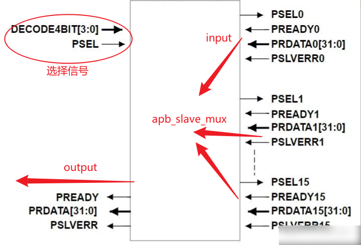
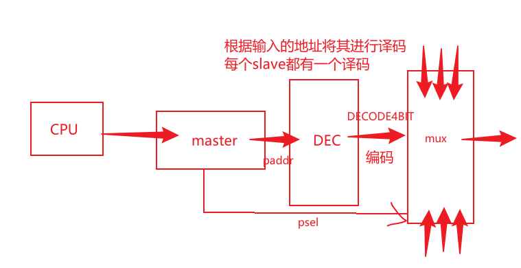
基于APB slave mux我们可以快速地将多个apb slave连接在APB上面。在实际的设计当中都是采用这样的方式连接多个APB slave的
- DECODE4BIT - 可以理解为master接收到地址之后,进行译码,通过mux进行选择那个APB slave
module apb_slave_mux
#(
    // 定义16个端口的使能信号,默认为1,保证每个slave端口信号能够输入
    parameter PORT0_ENABLE = 1,
    parameter PORT1_ENABLE = 1,
    parameter PORT2_ENABLE = 1,
    parameter PORT3_ENABLE = 1,
    parameter PORT4_ENABLE = 1,
    parameter PORT5_ENABLE = 1,
    parameter PORT6_ENABLE = 1,
    parameter PORT7_ENABLE = 1,
    parameter PORT8_ENABLE = 1,
    parameter PORT9_ENABLE = 1,
    parameter PORT10_ENABLE = 1,
    parameter PORT11_ENABLE = 1,
    parameter PORT12_ENABLE = 1,
    parameter PORT13_ENABLE = 1,
    parameter PORT14_ENABLE = 1,
    parameter PORT15_ENABLE = 1
)
(
    // 选择信号
    input wire  [3:0]       DECODE4BIT,
    input wire              PSEL,

    // 每个slave的输入输出信号
    output wire             PSEL0,
    input wire              PREADY0,
    input wire  [31:0]      PRDATA0,
    input wire              PSLVERR0,

    output wire             PSEL1,
    input wire              PREADY1,
    input wire  [31:0]      PRDATA1,
    input wire              PSLVERR1,


    output wire             PSEL2,
    input wire              PREADY2,
    input wire  [31:0]      PRDATA2,
    input wire              PSLVERR2,

    output wire             PSEL3,
    input wire              PREADY3,
    input wire  [31:0]      PRDATA3,
    input wire              PSLVERR3,

    output wire             PSEL4,
    input wire              PREADY4,
    input wire  [31:0]      PRDATA4,
    input wire              PSLVERR4,

    output wire             PSEL5,
    input wire              PREADY5,
    input wire  [31:0]      PRDATA5,
    input wire              PSLVERR5,

    output wire             PSEL6,
    input wire              PREADY6,
    input wire  [31:0]      PRDATA6,
    input wire              PSLVERR6,


    output wire             PSEL7,
    input wire              PREADY7,
    input wire  [31:0]      PRDATA7,
    input wire              PSLVERR7,

    output wire             PSEL8,
    input wire              PREADY8,
    input wire  [31:0]      PRDATA8,
    input wire              PSLVERR8,

    output wire             PSEL9,
    input wire              PREADY9,
    input wire  [31:0]      PRDATA9,
    input wire              PSLVERR9,

    output wire             PSEL10,
    input wire              PREADY10,
    input wire  [31:0]      PRDATA10,
    input wire              PSLVERR10,

    output wire             PSEL11,
    input wire              PREADY11,
    input wire  [31:0]      PRDATA11,
    input wire              PSLVERR11,

    output wire             PSEL12,
    input wire              PREADY12,
    input wire  [31:0]      PRDATA12,
    input wire              PSLVERR12,

    output wire             PSEL13,
    input wire              PREADY13,
    input wire  [31:0]      PRDATA13,
    input wire              PSLVERR13,

    output wire             PSEL14,
    input wire              PREADY14,
    input wire  [31:0]      PRDATA14,
    input wire              PSLVERR14,

    output wire             PSEL15,
    input wire              PREADY15,
    input wire  [31:0]      PRDATA15,
    input wire              PSLVERR15


);


// 产生使能信号
    wire [15:0] en = {
        (PORT15_ENABLE ==1),
        (PORT14_ENABLE ==1),
        (PORT13_ENABLE ==1),
        (PORT12_ENABLE ==1),
        (PORT11_ENABLE ==1),
        (PORT10_ENABLE ==1),
        (PORT9_ENABLE ==1),
        (PORT8_ENABLE ==1),
        (PORT7_ENABLE ==1),
        (PORT6_ENABLE ==1),
        (PORT5_ENABLE==1),
        (PORT4_ENABLE==1),
        (PORT3_ENABLE==1),
        (PORT2_ENABLE==1),
        (PORT1_ENABLE==1),
        (PORT0_ENABLE==1)
    };

    wire [15:0] dec = {
        (DECODE4BIT == 4'd15),
        (DECODE4BIT == 4'd14),
        (DECODE4BIT == 4'd13),
        (DECODE4BIT == 4'd12),
        (DECODE4BIT == 4'd11),
        (DECODE4BIT == 4'd10),
        (DECODE4BIT == 4'd9),
        (DECODE4BIT == 4'd8),
        (DECODE4BIT == 4'd7),
        (DECODE4BIT == 4'd6),
        (DECODE4BIT == 4'd5),
        (DECODE4BIT == 4'd4),
        (DECODE4BIT == 4'd3),
        (DECODE4BIT == 4'd2),
        (DECODE4BIT == 4'd1),
        (DECODE4BIT == 4'd0)
    };

    // PSEL0 - 表示输出的salve选择信号
    // PSEL - 拉高表示master要选择一个slave
    // en[0] - 对应端口使能,默认是为1
    // dec[0] - 对应decode4bit编码值与相应的slave编码值一致
    assign PSEL0 = PSEL & en[0] & dec[0];
    assign PSEL1 = PSEL & en[1] & dec[2];
    assign PSEL2 = PSEL & en[2] & dec[2];
    //.......省略中间//省略3~15
    assign PSEL15 = PSEL & en[15] & dec[15];

    //省略3~15
    assign PREADY  = ~PSEL |
                   ( dec[ 0]  & (PREADY0  | ~en[ 0]) ) |
                   ( dec[ 1]  & (PREADY1  | ~en[ 1]) ) |
                   ( dec[ 2]  & (PREADY2  | ~en[ 2]) ) |
                    //....
                   (dec[15] & (PREADY15| ~en[15]));
    //省略3~15
     assign PSLVERR = ( PSEL0  & PSLVERR0  ) |
                      ( PSEL1  & PSLVERR1  ) |
                      ( PSEL2  & PSLVERR2  ) |
                      //...
                      ( PSEL15  & PSLVERR15  ) ;
    //省略3~15
    assign PRDATA  = ( {32{PSEL0 }} & PRDATA0  ) |
                     ( {32{PSEL1 }} & PRDATA1  ) |
                     ( {32{PSEL2 }} & PRDATA2  ) |
                     //...
                     ( {32{PSEL15 }} & PRDATA15  ) ;

endmodule
- 根据PSEL是否有效以及DECODE4BIT的值,完成16选1,PSEL0~PSEL15有一个或者0个拉高。
- PREADYm默认为1,当PSEL为1的时候,根据译码结果选择相应的PREADY信号(当端口没有使能的时候en[x] == 0, 对应的PREADYx信号不会被选择)。
- PSLVERR和PRDATA,选中谁就取谁的